Motor, stator, wire and manufacturing method of the same

a manufacturing method and motor technology, applied in the direction of windings, dynamo-electric components, synchronous machines, etc., can solve the problems of difficult manipulation, and stoppage of compressor components such as air conditioners

Active Publication Date: 2008-06-12
NIPPON DENSAN CORP
View PDF6 Cites 65 Cited by
  • Summary
  • Abstract
  • Description
  • Claims
  • Application Information

AI Technical Summary

Benefits of technology

[0012]Other features, elements, steps, characteristics and advantages of the present invention will become more appar

Problems solved by technology

However, when a compressor is activated by the engine of such vehicle, each time the engine stops, the components activated by the compressor, such as an air conditioner, also stop.
Conventionally, the wire whose large and recta

Method used


Image

  • Motor, stator, wire and manufacturing method of the same
  • Motor, stator, wire and manufacturing method of the same
  • Motor, stator, wire and manufacturing method of the same

Examples


Embodiment Construction

[0037]Note that in the description of preferred embodiments of the present invention herein, words such as upper, lower, left, right, upward, downward, top and bottom for describing positional relationships between respective members and directions merely indicate positional relationships and direction in the drawings. Such words do not indicate positional relationships and directions of the members mounted in an actual device. Also note that reference numerals, figure numbers and supplementary descriptions are shown below for assisting the reader in finding corresponding components in the description of the preferred embodiments below to facilitate the understanding of the present invention. It should be understood that these expressions in no way restrict the scope of the present invention.

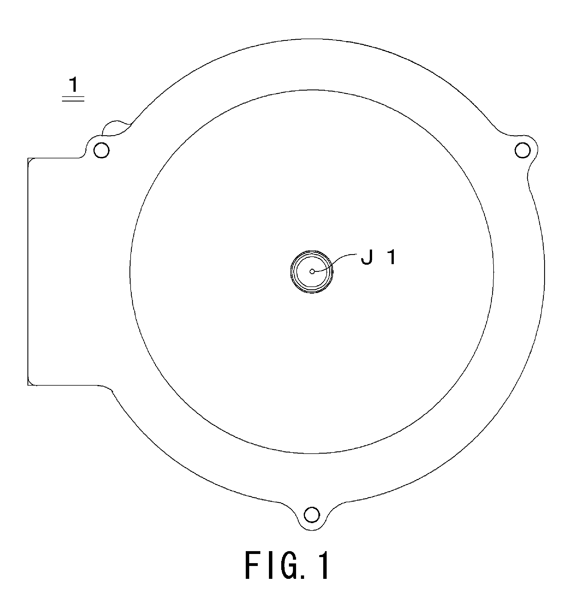
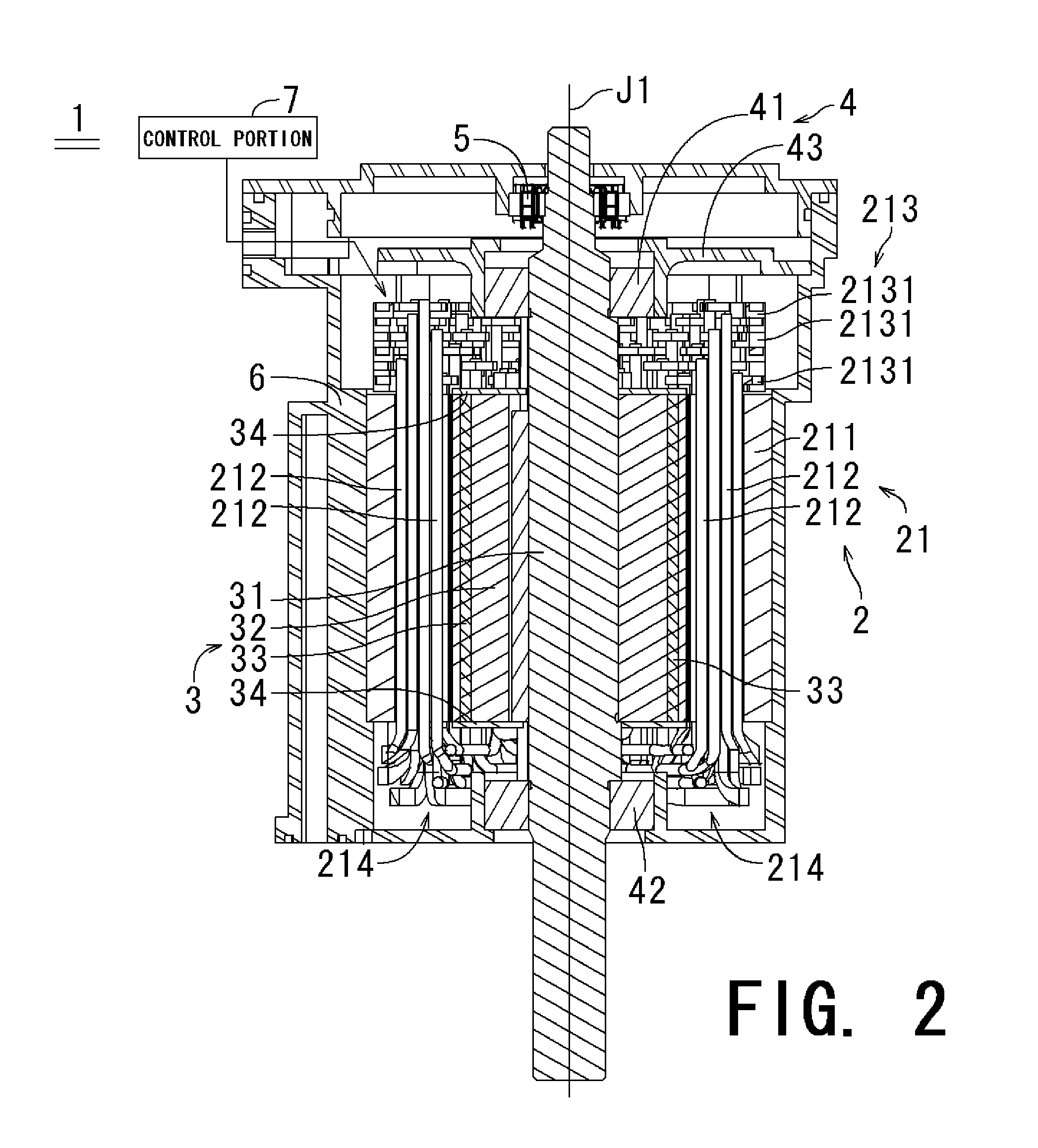
[0038]FIG. 1 is a schematic plan view of an exterior of a motor 1 according to a first preferred embodiment of the present invention. FIG. 2 is a schematic cross sectional view of the motor 1.

[0...


PUM

PropertyMeasurementUnit
Diameteraaaaaaaaaa
Areaaaaaaaaaaa
Diameteraaaaaaaaaa

Abstract

A stator of a motor includes a plurality of busbar plates, each laminated above a stator core in an axial direction and connected to a plurality of wires having a substantially U-shaped configuration. Each busbar plate includes a plurality of busbars arranged in a circumferential direction, and a busbar holder of insulating quality to which the plurality of busbars are integrally affixed. The wires include a line portion, and a connecting end portion having a substantially columnar shape protruding from an end surface of the line portion. The busbar makes contact with the end surface of the line portion and is connected by welding to the connecting end portion.

Description

BACKGROUND OF THE INVENTION[0001]1. Field of the Invention[0002]The present invention relates to a motor, a stator of the motor, a configuration of a wire in the stator, and a manufacturing method of the same.[0003]2. Description of the Related Art[0004]In recent years, various components and mechanisms used in a vehicle have been developed with a specific focus on environmental concerns (e.g., energy efficiency, reduction of carbon dioxide emission, and the like). One of such mechanisms is an “idling stop” mechanism which allows an engine of a vehicle that is not in motion to automatically stop in order to reduce the carbon dioxide emission.[0005]However, when a compressor is activated by the engine of such vehicle, each time the engine stops, the components activated by the compressor, such as an air conditioner, also stop. In order to avoid such inconvenience, the compressor of the components, such as an air conditioner, is operated by a motor (e.g., IPM (Interior Permanent Magne...

Claims


Application Information

Patent Timeline
IPC IPC(8): H02K3/50H02K15/085H02K15/08H02K3/04
CPCH02K3/12H02K15/0081H02K15/085Y10T29/49009
Inventor FUJII, YOSHIOYAMADA, YOSUKESUZUKI, HIDEAKI
Owner NIPPON DENSAN CORP
Why Eureka
Try Eureka