Current sensor

a current sensor and sensor technology, applied in the direction of electric variable regulation, process and machine control, instruments, etc., can solve the problems of high loss provided by the circuit, resistor b>102/b> not being easily integrated, and low loss

Active Publication Date: 2008-06-12
SILICON LAB INC
View PDF31 Cites 29 Cited by
  • Summary
  • Abstract
  • Description
  • Claims
  • Application Information

AI Technical Summary

Benefits of technology

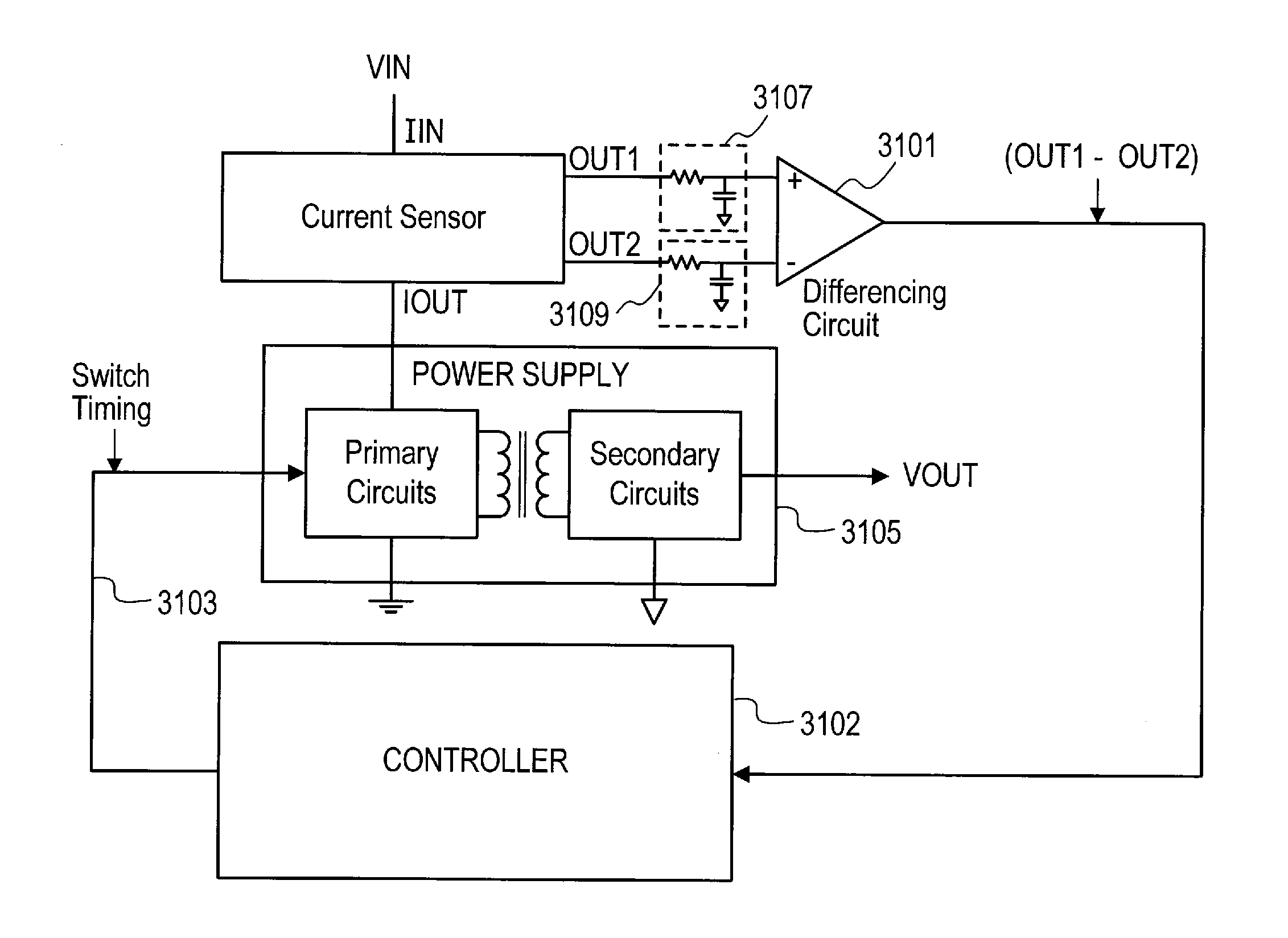
[0011]Accordingly, in one embodiment of the present invention, a current sensor is provided that includes a sensing circuit for sensing current and supplying indications thereof. The current sensor also includes a plurality of output terminals coupled to the sensing circuit. The plurality of output terminals alternately supply respective indications of the sensed current according to control signals supplied to the apparatus. The number of output terminals supplying indications of the sensed current may be, e.g., two, four, or more.
[0012]The apparatus may further include a plurality of input terminals coupled to receive respective ones of the control signals and reset logic coupled to the input terminals to provide a reset signal to the sensing circuit according to the control signals. The control signals are typically also coupled to control current flow through a power supply.
[0013]In an embodiment, the apparatus is operable in a first mode in which the reset logic utilizes four time-varying control signals to determine the reset signal to reset the sensing circuit and is operable in a second mode in which the reset logic is responsive to two time-varying control signals to determine the reset signal to reset the sensing circuit.
[0014]In another embodiment a current sensor is provided that is operable to supply indications of sensed current on only one output terminal in

Problems solved by technology

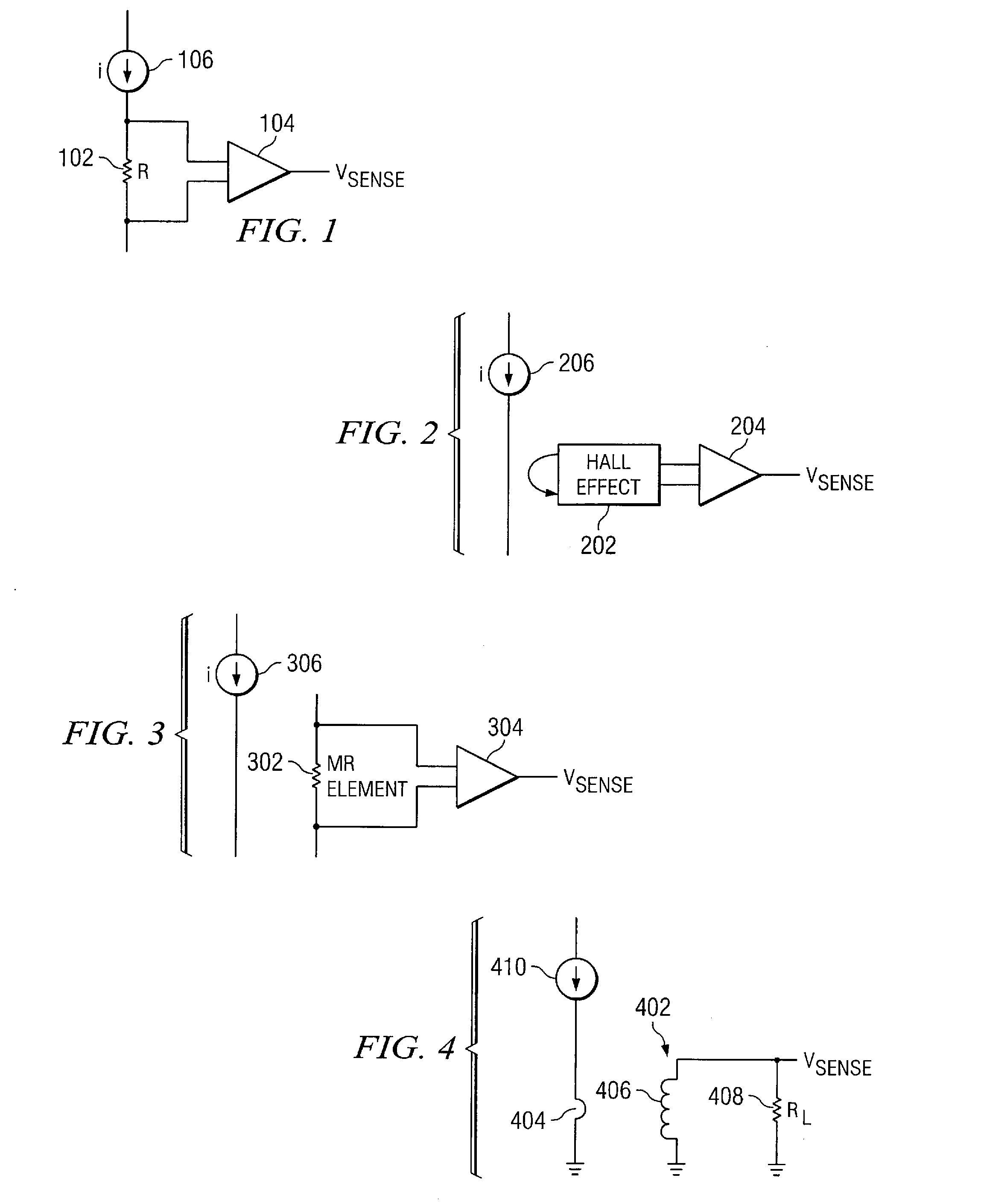
However, a drawback of this approach is the high loss provided by the circuit.
While this type of circuit may be used to sense current in direct current (DC) applications, the resistor 102 has usually not been capable of being readily integrated.
While this approach has a relatively low loss and may be used to detect direct current (DC), the use of the Hall effect device 202 generally provides a circuit having a higher cost.
Furthermore, accuracy and noise issues are generally greater in current sensors that implement a Hall device,

Method used


Image

  • Current sensor
  • Current sensor
  • Current sensor

Examples


Embodiment Construction

)

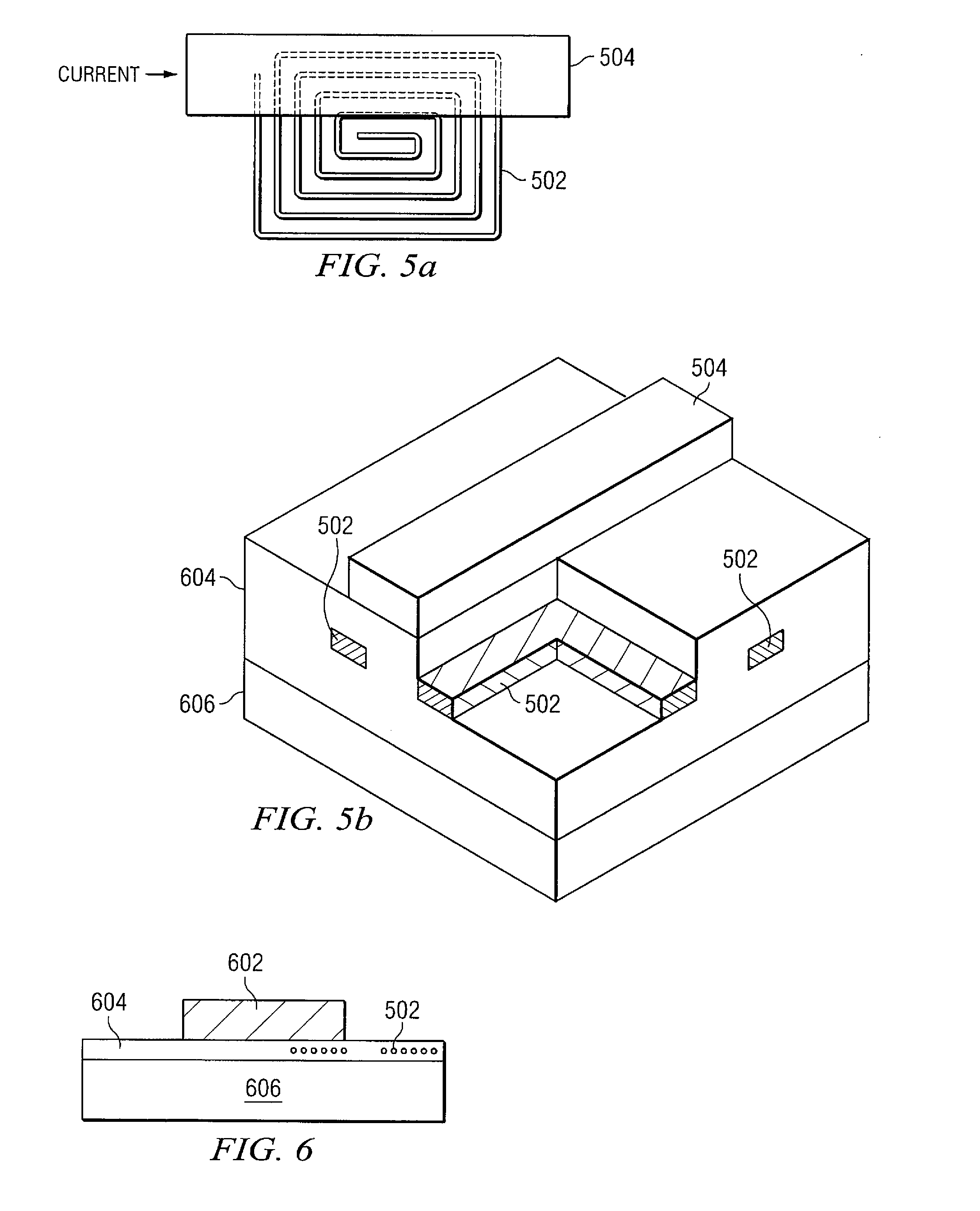
[0055]Referring now to the drawings, and more particularly to FIG. 5a, there is illustrated a coil 502 in close proximity with a large current carrying wire (or conductor) 504 such that the coil 502 and current carrying wire 504 act as coupled inductors. The coupled inductors, along with on-chip electronics, which will be discussed herein below, allow for the creation of the VSENSE signal which is proportional to an input current ip in a manner that has very low loss, is very small and is a low cost implementation. This generally provides a better solution than the implementations described with respect to FIGS. 1-4. The current provided through the current carrying wire 504 may be up to, for example, 10 A. The coil 502 is placed near the current carrying wire 504 in order to create inductive coupling between the wire 504 and coil 502. As shown, the wire 504 overlaps only one side of the coil 502 such that the windings are all going the same way and the magnetic flux adds together....


PUM


Abstract

A current sensor includes a sensing circuit for sensing current and supplying indications thereof. The current sensor also includes two or more output terminals coupled to the sensing circuit that alternately supply respective indications of the sensed current according to control signals supplied to the current sensor.

Description

BACKGROUND[0001]1. Field of the Invention[0002]The present invention relates to current sensors, and more particularly, to current sensors useful in applications such as power supplies.[0003]2. Description of the Related Art[0004]Within various circuit implementations, such as power supplies, there is often a need to detect a current provided at a particular point within a circuit. For example, a detected current may be used as feedback for controlling other parts of a circuit. Various techniques are presently used to sense currents within electronic circuits, but each of these techniques has shortcomings. One approach, illustrated in FIG. 1, utilizes a resistor 102 connected across the inputs of an operational amplifier 104 to provide a voltage VSENSE that may be used to determine a current 106. A low value resistor, in the range of 10 mOhms, may be implemented. However, a drawback of this approach is the high loss provided by the circuit. The high loss may be mitigated by reducing...

Claims


Application Information

Patent Timeline
IPC IPC(8): G05F5/04G01R19/15
CPCG01R19/0092H01L2924/181H01L2224/48091H01L2224/4826H01L2224/49111H01L2224/49171H01L2224/45147H01L2924/00014H01L2924/00012
Inventor ALFANO, DONALD E.DUPUIS, TIMOTHY J.
Owner SILICON LAB INC
Why Eureka
Try Eureka