Multi-frequency antenna

a multi-frequency antenna and antenna technology, applied in the direction of antenna earthing, radiating element structural forms, resonance antennas, etc., can solve the problems of high cost of external antennas, poor efficiency effect, and building antennas inside spatially limited computer devices, so as to improve good wireless signal transmission and reception efficiency, and increase the frequency response of the first and second

Active Publication Date: 2008-06-12
WISTRON NEWEB
View PDF3 Cites 20 Cited by
  • Summary
  • Abstract
  • Description
  • Claims
  • Application Information

AI Technical Summary

Benefits of technology

[0010]The multi-frequency antenna is disposed in a three-dimensional space with a first surface, a second surface, a third surface, and a fourth surface. The second surface is roughly perpendicular to the first surface. The third surface is roughly parallel to the second surface, and perpendicular to the first surface. The fourth surface is roughly parallel to the first surface, and roughly perpendicular to the second and third surfaces. The multi-frequency antenna includes a grounding element, a first conductive member, a first radiation member, and a second radiation member. The grounding element is disposed on the first surface. The first conductive member has a conductive component and a ground connecting component. The ground connecting component is disposed on the second surface, with one edge connected to the conductive component and the other edge connected to the grounding element. The first radiation member receives signals of the first frequency and connects to the conductive component. The first radiation member distributes over the second surface and the third surface. The second radiation member receives signals of the second frequency and connects to the conductive component at a predetermined distance from the first radiation member. The second radiation member is disposed on the second, third, and fourth surfaces. The multi-frequency antenna is further installed with a passive element and a parasitic structure to increase the frequency response of the first and second radiation members.
[0011]Therefore, the disclosed multi-frequency antenna can provide good wireless signal transmission and reception efficiency even in a limited space of a portable computer device.

Problems solved by technology

Such external antennas have higher costs because they are exposed to the environment and more susceptible to damages.
However, building the antenna inside a spatially limited computer device may have bad effects on its efficiency.

Method used


Image

  • Multi-frequency antenna
  • Multi-frequency antenna
  • Multi-frequency antenna

Examples


Embodiment Construction

[0028]The present invention will be apparent from the following detailed description, which proceeds with reference to the accompanying drawings, wherein the same references relate to the same elements.

[0029]An embodiment of the invention is a multi-frequency antenna disposed in a portable electronic device with the wireless communication function, such as a laptop computer or a personal digital assistant (PDA). Such a multi-frequency antenna can receive signals in at least two frequency bands. For the convenience of description, this specification refers exclusively to their central frequencies unless specified. That is, the specification uses a first frequency and a second frequency to represent the two bands. Any person skilled in the art can vary different parameters in the antenna design for different applications according to the need.

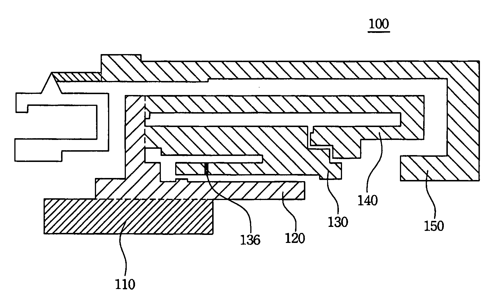
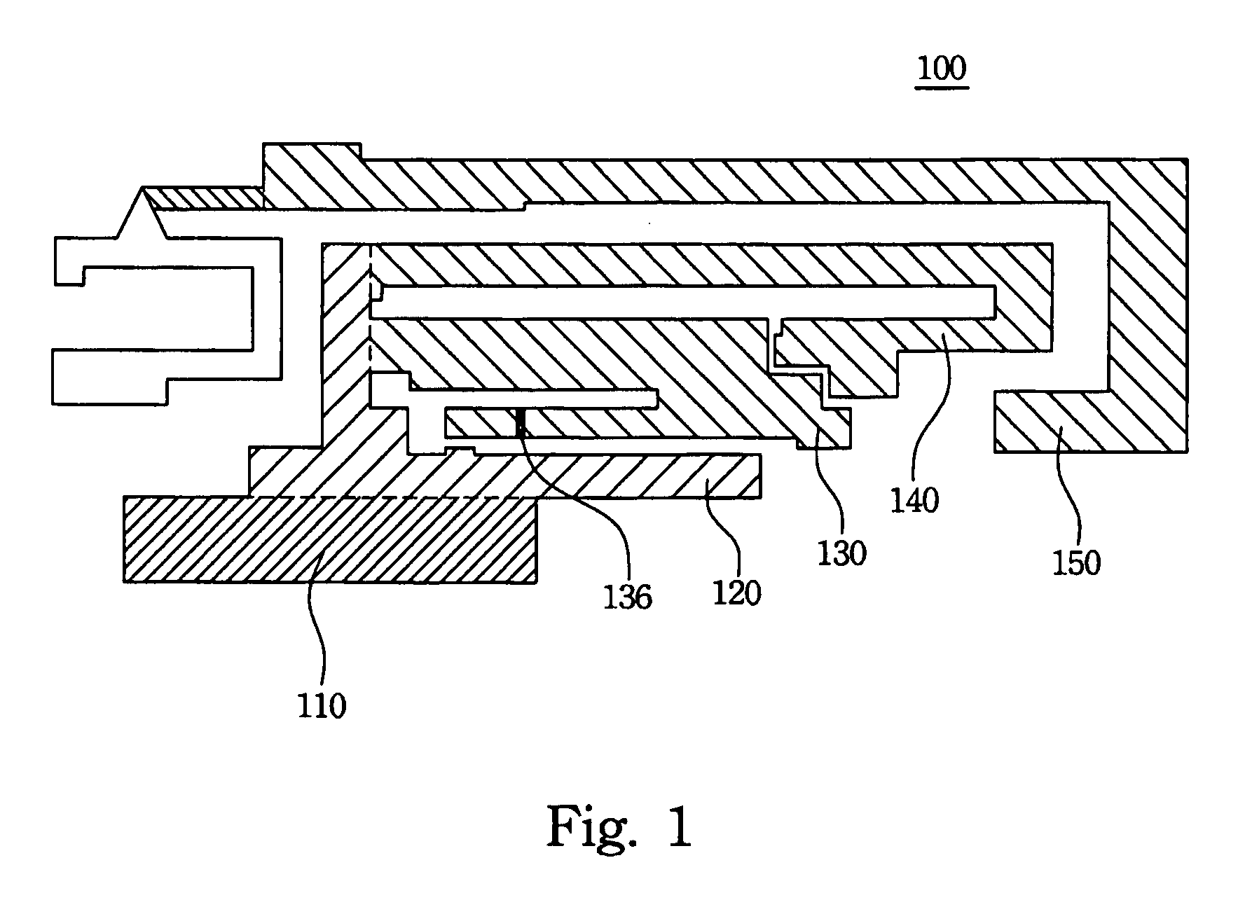
[0030]A planar view of the multi-frequency antenna according to an embodiment of the invention is shown in FIG. 1. In this embodiment, the multi...


PUM


Abstract

A multi-frequency antenna for receiving a first frequency and second frequency signals comprises a grounding element, a first conductive member, a first radiation member, and a second radiation member. The first conductive member connects to the grounding element. The first radiation member and the second radiation member connect to the first conductive member separately. The multi-frequency antenna further comprises a parasitic structure. The parasitic structure structurally encircles the second radiation member and the encirclement is a partial encirclement. Moreover, the parasitic structure connects to the grounding element.

Description

RELATED APPLICATIONS[0001]This application claims priority to Taiwan Application Serial Number 95145782, filed Dec. 7, 2006, which is herein incorporated by reference.BACKGROUND OF THE INVENTION[0002]1. Field of Invention[0003]The invention relates to an antenna structure and, in particular, to a multi-frequency antenna structure.[0004]2. Related Art[0005]The connections and communications among various wireless networks, such as wireless personal area networks (WPAN), wireless local area networks (WLAN), and wireless wide area networks (WWAN), or system devices can be implemented with the antennas therein.[0006]Generally speaking the antennas of wireless devices can be external or internal. For example, the external antennas of some laptop computers are disposed at the top of the monitors or on the PCMCIA cards. Such external antennas have higher costs because they are exposed to the environment and more susceptible to damages. The other design is to embed antennas inside the lapto...

Claims


Application Information

Patent Timeline
Patent Type & Authority Applications(United States)
IPC IPC(8): H01Q9/04H01Q5/10
CPCH01Q1/243H01Q5/392H01Q5/371
Inventor LAI, YING-JIUNNHUANG, JIUNN-MINGTSENG, KUAN-HSUEH
Owner WISTRON NEWEB
Why Eureka
Try Eureka