Liquid recording head

a liquid recording head and recording head technology, applied in printing and other directions, can solve the problems of difficult to compatibly realize the performance of both ejection outlets cannot be readily realized compatibly, and the accompanying of the conventional recording head, etc., and achieve the effect of simple and inexpensive ink jet recording head and droplet ejection outlet larg

Inactive Publication Date: 2008-06-12
CANON KK
View PDF8 Cites 17 Cited by
  • Summary
  • Abstract
  • Description
  • Claims
  • Application Information

AI Technical Summary

Benefits of technology

[0040]According to the present invention, it is possible to compatibly realize both of performances of ejection from a small droplet ejection outlet and a large droplet ejection outlet in a proper state even when a difference in ejection amount between the small droplet ejection outlet and the large droplet ejection outlet is increased. Further, it is possible to realize simply and inexpensively an ink jet recording head achieving the above effect with accuracy. Further, according to the present invention, it is possible to provide an ink jet recording head capable of retaining a normal ejection state by keeping a meniscus vibration of a small droplet at a proper level even in a constitution in which small droplet ejection outlets and large droplet ejection outlets are alternately arranged at both sides of a common liquid chamber.

Problems solved by technology

However, the conventional recording heads are accompanied with the following problems (A) and (B).
When a difference between an amount of ejection (ejection amount) of the small droplet ejection outlet and an ejection outlet of the large droplet ejection outlet is increased, it is difficult to compatibly realize ejection performances of both ejection outlets on condition that the distance (OH) from the substrate surface to the ejection outlet and the flow passage height (h) are identical with respect to both of the small droplet ejection outlet and the large droplet ejection outlet.
However, when the small droplet ejection amount is less than 2 pl, a difference between values of (OH) and (h) capable of providing a proper characteristic with respect to the large droplet ejection outlet and those with respect to the small droplet ejection outlet is increased, so that the performances of the both ejection outlets cannot be readily realized compatibly.
Particularly, in a recording head of a BTJ (bubble through jet) type wherein a bubble communicates with ambient air, a bubble in the small droplet ejection outlet is less liable to communicate with the ambient air to unstable an ejection state, so that print is liable to be disturbed.
However, in order to keep the performance of the small droplet ejection outlet at a proper level, when the distance (OH) is simply decreased, the following new problems (1) and (2) arise in turn.
As a result, an ink refilling time from current ink droplet ejection to subsequent ink droplet ejection is increased, so that an upper limit of an ejection frequency is lowered, thus resulting in a low throughput.
The ink droplet ejected from the large droplet ejection outlet is used for printing at a high density portion of a print, so that this problem is particularly noticeable.
For this reason, trailing of the ejected ink droplet occurs at a portion toward the common liquid chamber, so that the trailing portion is liable to interfere with an edge of the ejection outlet.
As a result, a dew-like ink is liable to be deposited around the ejection outlet edge.
As a result, a meniscus at the small droplet ejection outlet is vibrated, so that ejection from the small droplet ejection outlet is liable to be disturbed.

Method used


Image

  • Liquid recording head
  • Liquid recording head
  • Liquid recording head

Examples


embodiment 1

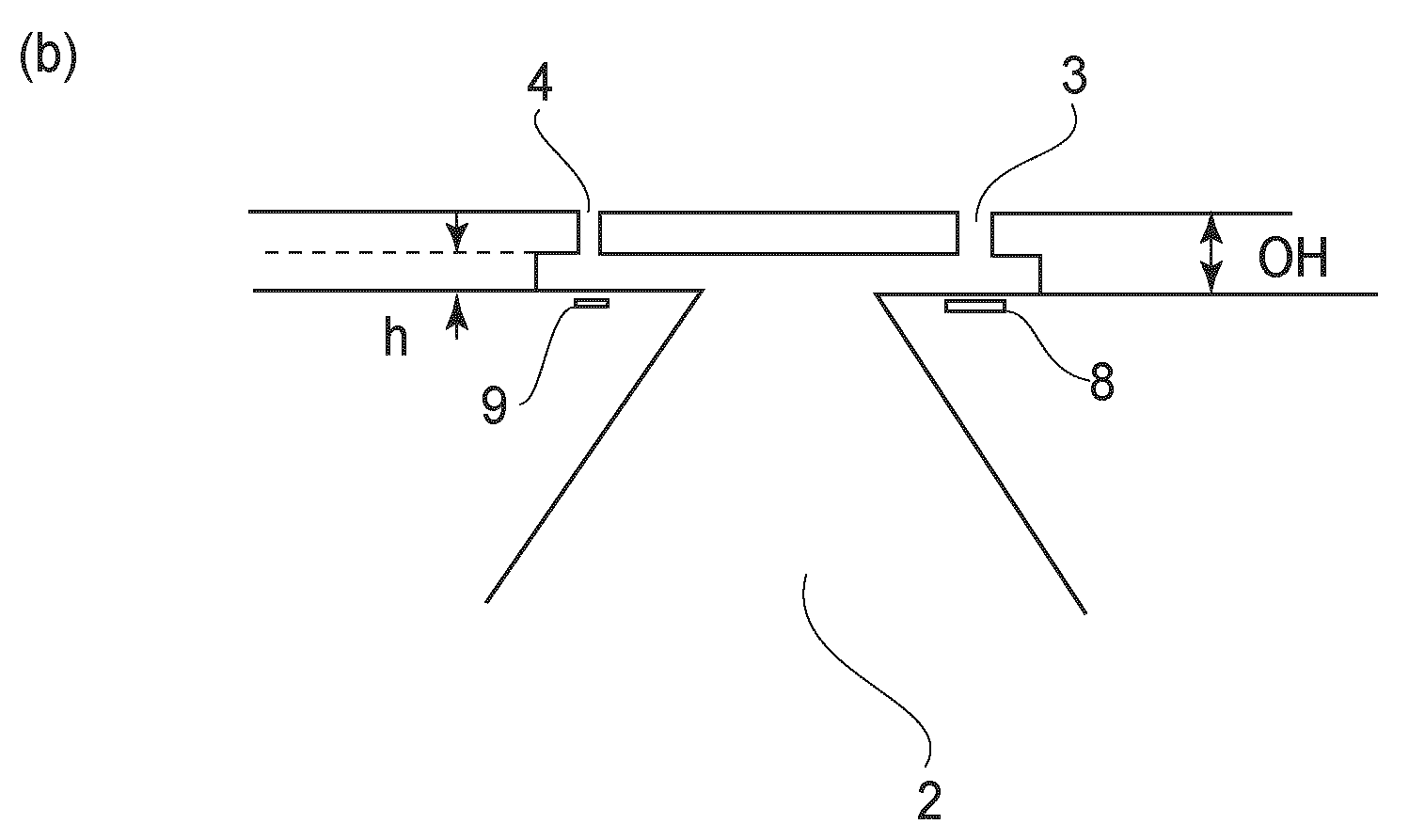
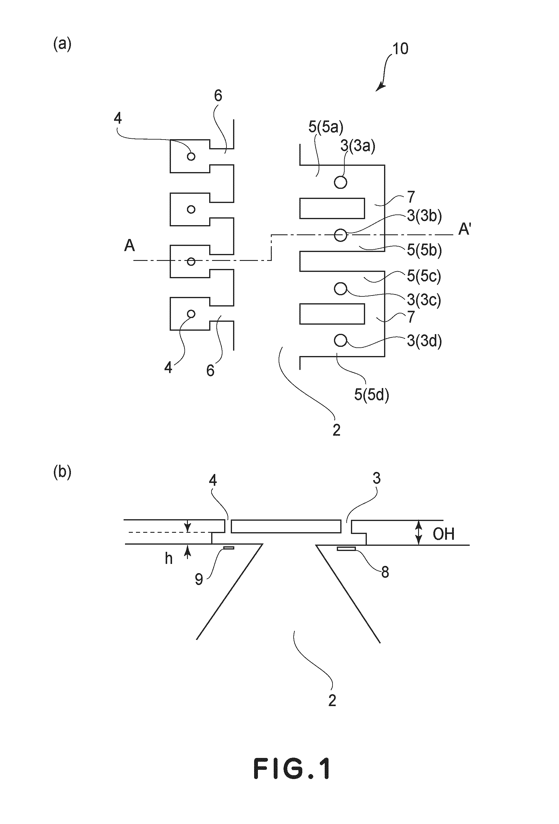
[0046]Hereinbelow, an embodiment of the liquid recording head (ink jet recording head) of the present invention will be described. FIG. 1(a) is a partially enlarged schematic plan view showing ejection outlets, flow passages and a common liquid chamber in an ink jet recording head 10 in this embodiment. FIG. 1(b) is a schematic sectional view taken along A-A′ line indicated in FIG. 1(a).

[0047]As shown in FIG. 1(a), in the recording head 10 in this embodiment, a plurality of large droplet ejection outlets 3 (3a to 3d) is arranged in a line at one side of a common liquid chamber 2 in a longitudinal direction of the common liquid chamber 2 and a plurality of small droplet ejection outlets 4 is arranged in a line at the other side of the common liquid chamber 2 in the longitudinal direction. The large droplet ejection outlets 3 (3a to 3d) communicate with the common liquid chamber 2 through large droplet flow passages 5 (5a to 5d), respectively. Each small droplet ejection outlet 4 comm...

embodiment 2

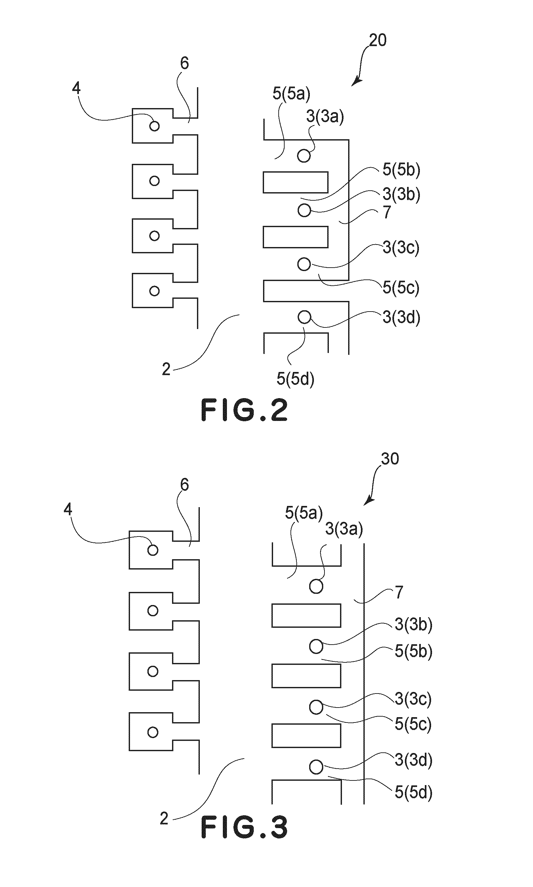
[0058]Another Embodiment of the ink jet recording head of the present invention will be described. FIG. 2 is a partially enlarged schematic plan view showing ejection outlets, flow passages and a common liquid chamber in an ink jet recording head 20 in this embodiment.

[0059]A base constitution of the recording head 20 in this embodiment is in common with the recording head 10 in Embodiment 1. Therefore, the common constitution is omitted from the following description by using identical reference numerals. The recording head 20 in this embodiment is characterized in that three large droplet flow passages 5 and connected. More specifically, a large droplet flow passage 5a provided to a large droplet ejection outlet 3a, a large droplet flow passage 5b provided to a large droplet ejection outlet 3b, and a large droplet flow passage 5c provided to a large droplet ejection outlet 3c are connected with each other by a sub-flow passage 7. In other words, with respect to one large droplet e...

embodiment 3

[0062]Another Embodiment of the ink jet recording head of the present invention will be described. FIG. 3 is a partially enlarged schematic plan view showing ejection outlets, flow passages and a common liquid chamber in an ink jet recording head 30 in this embodiment.

[0063]A base constitution of the recording head 30 in this embodiment is in common with the recording head 10 in Embodiment 1. Therefore, the common constitution is omitted from the following description by using identical reference numerals. The recording head 30 in this embodiment is characterized in that all the plurality of large droplet flow passages 5 and connected. In FIG. 3, only large droplet flow passages 5a to 5d are shown but other large droplet flow passages are also connected by a single sub-flow passage 7. In other words, in this embodiment, all of large droplet ejection outlets 3 are connected each other through the flow passages 5 and 7.

[0064]The large droplet ejection outlets 3 in the recording head 1...


PUM


Abstract

A liquid recording head for effecting recording by ejecting droplets from a plurality of ejection outlets formed on a substrate is provided. The liquid recording head includes a plurality of large droplet ejection outlets each having a relatively large ejection amount, a plurality of small droplet ejection outlets each having in a relatively small ejection amount, energy generating elements for generating energy for ejecting the droplets from the plurality of large droplet ejection outlets and the plurality of small droplet ejection outlets, a liquid chamber for retaining liquid to be ejected from the plurality of large droplet ejection outlets or the plurality of small droplet ejection outlets, at least two first flow passages for establishing communication between the liquid chamber and each of first ejection outlets; and a second flow passage for establishing communication between the liquid chamber and at least two second ejection outlets.

Description

FIELD OF THE INVENTION AND RELATED ART[0001]The present invention relates to a liquid recording head.[0002]FIGS. 10 to 13 shows conventional ink jet recording heads described in U.S. Pat. No. 6,830,317. In the recording heads shown in these figures, a plurality of large droplet ejection outlets 100 having a relatively large ejection amount and a plurality of small droplet ejection outlets 101 having a relatively small ejection amount are formed on the same substrate. Further, a common liquid chamber 102 common to all the ejection outlets is provided. The plurality of large droplet ejection outlets 100 and the common liquid chamber 102 establish one-to-one communication through a large droplet flow passage 103 provided for each large droplet ejection outlet 100. On the other hand, the plurality of small droplet ejection outlets 101 and the common liquid chamber 102 establish one-to-one communication through a small droplet flow passage 104 provided for each small droplet ejection out...

Claims


Application Information

Patent Timeline
Patent Type & Authority Applications(United States)
IPC IPC(8): B41J2/05
CPCB41J2/1404B41J2/1412B41J2002/14475B41J2002/14467B41J2/1433
Inventor TSUCHII, KENMIZUTANI, MICHINARI
Owner CANON KK
Why Eureka
Try Eureka