Camera having a focus adjusting system and a face recognition function

Inactive Publication Date: 2008-06-12
ASAHI KOGAKU KOGYO KK
View PDF5 Cites 92 Cited by
  • Summary
  • Abstract
  • Description
  • Claims
  • Application Information

AI Technical Summary

Benefits of technology

[0008]The present invention provides a camera having a face recognition function and a contrast-detection focus adjusting sys

Problems solved by technology

However, if the focusing lens group starts moving from the near extremity to bring an object at infinity into focus or from the far extremity to bring an object at the shortest distance into focus in the focus search operation, a long period of time is required for the focus search operation, so that it takes time to bring an object into focus.
Additionally, in conventional cameras having a face recognition function, when re

Method used


Image

  • Camera having a focus adjusting system and a face recognition function
  • Camera having a focus adjusting system and a face recognition function
  • Camera having a focus adjusting system and a face recognition function

Examples


Example

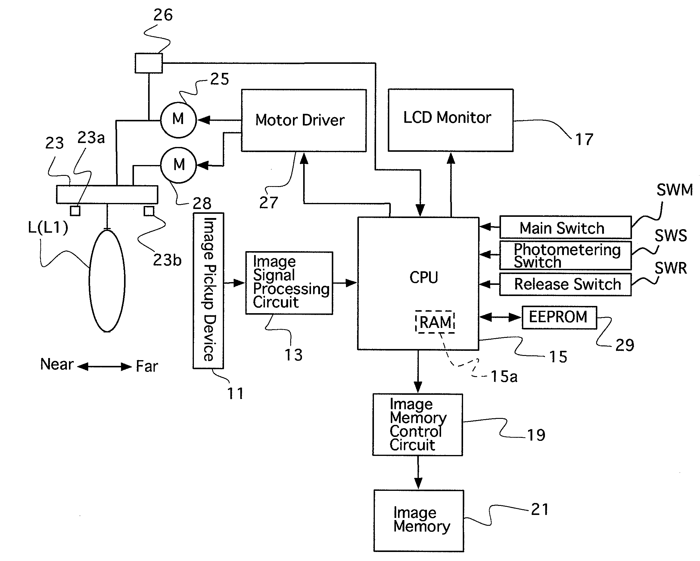
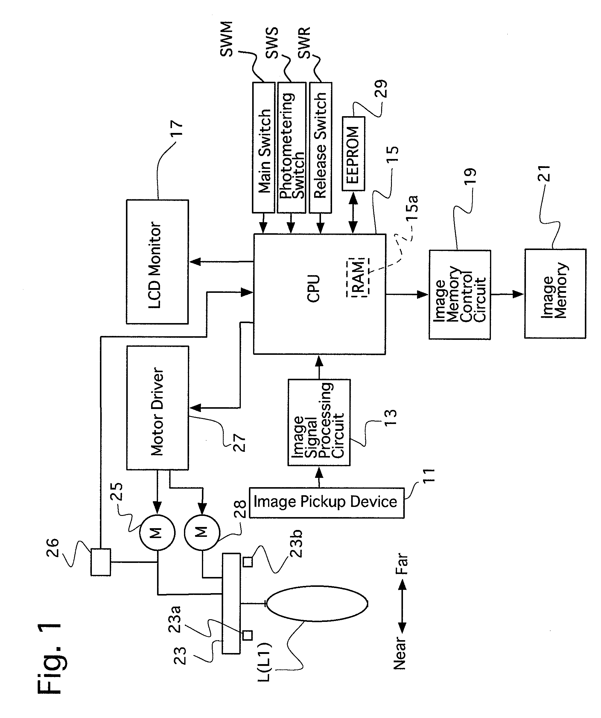
[0054]FIG. 1 is a block diagram of elements of a first embodiment of a compact digital camera having a contrast AF type of focus adjusting system (focusing system) to which the present invention is applied.

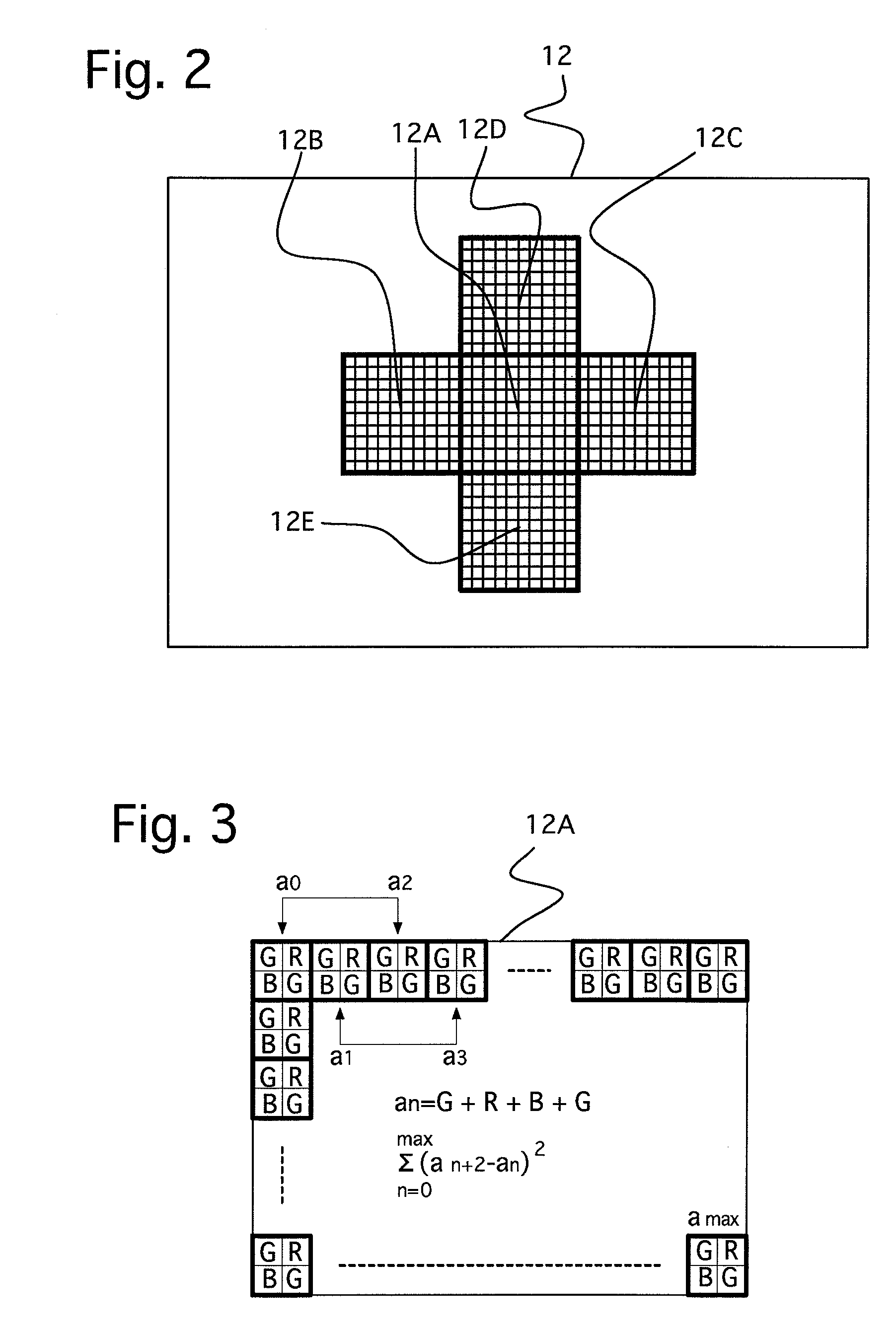
[0055]This digital camera is provided with a zoom lens (photographing optical system) L including a focusing lens group L1, and an image pickup device (CCD image sensor) 11. An object image is formed on a light receiving surface 12 of the image pickup device 11 via the zoom lens L. The image pickup device 11 includes a large number of pixels (photoelectric transducing elements) arranged in a two-dimensional matrix at predetermined intervals. The digital camera is further provided with an image signal processing circuit 13, a CPU 15, an LCD monitor 17, an image memory control circuit 19, and an image memory 21. Each pixel of the image pickup device 11 converts the incident light of an object image thereon into an electrical charge, and the electrical charges are accumulated (integr...

Example

[0105]The second embodiment the second embodiment of the digital camera will be discussed hereinafter. The second embodiment of the digital camera has a continuous face-recognition photographing mode. In the continuous face-recognition photographing mode, when two or more face images are recognized, a focusing operation and an image capturing operation are performed sequentially on each of the recognized face images. In the continuous face-recognition photographing mode, the face recognition is also carried out according to a known method. Namely, in the face recognition, flesh color (skin color) or face feature points (e.g., eye points, nose points and mouth points) are detected or the contours of faces are extracted to recognize faces in the entire image signal captured by the image pickup device 11. When the digital camera is in the continuous face-recognition photographing mode, upon detection of face images, the CPU 15 determines the positions of image areas including the face ...

Example

[0107]FIGS. 11A and 11B each show the relative position between the second embodiment of the digital camera 10 and persons to be photographed, and a manner of indicating the captured face images thereof on the LCD monitor 17. FIG. 11A shows the relationship between the screen 18 of the LCD monitor 17 and face images 101i and 102i of two persons 101 and 102, and areas (square areas) 101a and 102a which include the face images 101i and 102i, respectively, when the two persons 101 and 102 are in a short distance range. FIG. 11B shows the relationship between the screen 18 and face images 103i, 104i and 105i of three persons 103, 104 and 105, and areas (square areas) 103a, 104a and 105a which include the face images 103i, 104i and 105i, respectively, when the three persons 103, 104 and 105 are in a far distance range. As can be seen from these drawings, the face images 101i and 102i of the two persons 101 and 102, which are located closer to the digital camera 10 than the three persons ...


PUM


Abstract

A camera includes an image pickup device; a focus adjusting device which captures an object image at different positions while the focusing lens group is moved to detect an in-focus lens position, based on image signals of the object images, and the focusing lens group is moved to this in-focus lens position; and a face recognition device for recognizing a face image based on the image signals. When the face recognition device recognizes the face image, the focus adjusting device performs the focus search process toward the near extremity if the area size of the face image is smaller than a predetermined threshold value, and the focusing lens group moves toward the far extremity if the area size of the face image is equal to or greater than the predetermined threshold value.

Description

BACKGROUND OF THE INVENTION[0001]1. Field of the Invention[0002]The present invention relates to a focus adjusting system, and in particular relates to a camera having a contrast-detection focus adjusting system and a face recognition system.[0003]2. Description of the Prior Art[0004]Digital cameras with a contrast-detection focus adjusting system (focusing system) which detects a focus state (in-focus position) by performing a focus search operation are known in the art. In the focus search operation, images are captured consecutively at different positions of a focusing lens group while the focusing lens group is being moved stepwise from a search start extremity, which is one of the infinite focus position (far extremity / position for bringing an object at infinity into focus) and the closest (shortest) focus position (near extremity / position for bringing an object at the shortest distance in working range into focus), to a search end extremity (the other of the infinite focus pos...

Claims


Application Information

Patent Timeline
IPC IPC(8): H04N5/232
CPCG06K9/00255H04N5/23219H04N5/23212G06V40/166H04N23/673H04N23/61H04N23/611H04N23/635H04N25/134
Inventor NAKAHARA, NAOTO
Owner ASAHI KOGAKU KOGYO KK
Why Eureka
Try Eureka