Method and System for Shared High-Power Transmit Path for a Multi-Protocol Transceiver

a transceiver and high-power technology, applied in the field of wireless systems, can solve the problems of limiting the extent to which the physical dimensions of the portable device may be miniaturized, physical bulky devices, and disadvantages of such portable devices

Inactive Publication Date: 2008-06-12
AVAGO TECH WIRELESS IP SINGAPORE PTE
View PDF14 Cites 143 Cited by
  • Summary
  • Abstract
  • Description
  • Claims
  • Application Information

AI Technical Summary

Benefits of technology

[0017]FIG. 4 is an exemplary flow diagram for sharing a high-power transmit path for a multi-protocol transceiver, in accordance with an embodiment of the invention.
[0018]FIG. 5 is an exemplary flow diagram for sharing a high-power transmit path for a multi-protocol transceiver, in accordance with an embodiment of the invention.

Problems solved by technology

One limitation in the inexorable march toward increasing integration of wireless communications services in a single portable device is that the analog RF circuitry for each separate wireless communication service may be implemented in a separate integrated circuit (IC) device (or chip).
This may result in a number of disadvantages and / or limitations in such portable devices.
For example, the increasing chip count may limit the extent to which the physical dimensions of the portable device may be miniaturized.
Thus, the increasing integration may result in physically bulky devices, which may be less appealing to consumer preferences.
Along with an increasing IC component count, there may also be a corresponding rise in power consumption within the portable device.
This may present another set of disadvantages, such as increased operating temperature, and reduced battery life between recharges.

Method used


Image

  • Method and System for Shared High-Power Transmit Path for a Multi-Protocol Transceiver
  • Method and System for Shared High-Power Transmit Path for a Multi-Protocol Transceiver
  • Method and System for Shared High-Power Transmit Path for a Multi-Protocol Transceiver

Examples


Embodiment Construction

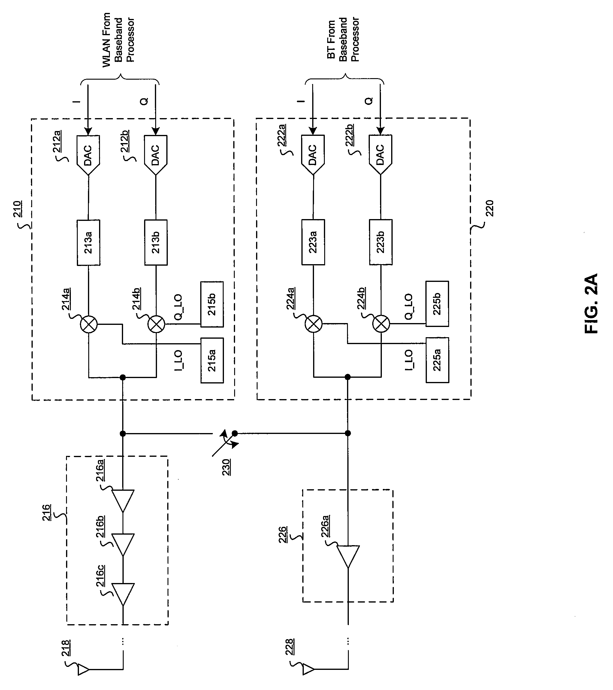
[0019]Certain embodiments of the invention may be found in a method and system for a shared high-power transmit path for a multi-protocol transceiver. Various embodiments of the invention may comprise sharing a first power amplifier with a first wireless signal and a second wireless signal. The first wireless signal may be modulated with IEEE 802.11x protocol, and the second wireless signal may be modulated with Bluetooth protocol. The first power amplifier may amplify the first wireless signal and / or the second wireless signal, where the first power amplifier may amplify the first wireless signal and the second wireless signal simultaneously.

[0020]A second power amplifier may be used to amplify the second wireless signal, where the first power amplifier may have a higher gain than the second power amplifier. Power may be reduced to the second power amplifier if the first power amplifier may be used to amplify the second wireless signal. The second wireless signal may be communicate...


PUM


Abstract

Aspects of a method and system for a shared high-power transmit path for a multi-protocol transceiver are disclosed. Aspects of one method may include sharing a first power amplifier with a WLAN signal and a Bluetooth signal. The first power amplifier may amplify the WLAN signal and/or the Bluetooth signal simultaneously, or individually. A second power amplifier may be used to amplify the Bluetooth signal, where the first power amplifier may have a higher gain than the second power amplifier. Power may be reduced to the second power amplifier in instances where the first power amplifier is used to amplify the Bluetooth signal. The Bluetooth signal may be communicated to the first power amplifier via a switching circuit, which may comprise one or more switching stages.

Description

CROSS-REFERENCE TO RELATED APPLICATIONS / INCORPORATION BY REFERENCE[0001]This application makes reference to, claims priority to, and claims the benefit of U.S. Provisional Application Ser. No. 60 / 868,818, filed on Dec. 6, 2006.[0002]The above stated application is hereby incorporated herein by reference in its entirety.FIELD OF THE INVENTION[0003]Certain embodiments of the invention relate to wireless systems. More specifically, certain embodiments of the invention relate to a method and system for a shared high-power transmit path for a multi-protocol transceiver.BACKGROUND OF THE INVENTION[0004]As mobile, wireless, and / or handheld portable devices increasingly become multifunctional, “all-in-one,” communication devices, these handheld portable devices integrate an increasingly wide range of functions for handling a plurality of wireless communication services. For example, a single handheld portable device may enable Bluetooth communications and wireless local area network (WLAN) ...

Claims


Application Information

Patent Timeline
Patent Type & Authority Applications(United States)
IPC IPC(8): H04B7/00
CPCH04B1/406H04B2001/0416H04W88/06H04W84/18H04W84/12Y02D30/70H04L12/28H04W84/10H04L9/40
Inventor MARHOLEV, BOJKOBEHZAD, ARYAPAN, MENG-ANANAND, SEEMA
Owner AVAGO TECH WIRELESS IP SINGAPORE PTE
Why Eureka
Try Eureka