Eureka AIR delivers breakthrough ideas for toughest innovation challenges, trusted by R&D personnel around the world.

Laser mirror for a ring laser gyroscope

a laser gyroscope and laser mirror technology, applied in the direction of optical resonator shape and construction, instruments, optical elements, etc., can solve the problem of degrading the rlg performan

Inactive Publication Date: 2008-06-12
HONEYWELL INT INC
View PDF8 Cites 4 Cited by
  • Summary
  • Abstract
  • Description
  • Claims
  • Application Information

AI Technical Summary

Problems solved by technology

This phenomenon of losing 633 nanometer photons in this manner degrades the RLG performance.

Method used


Image

  • Laser mirror for a ring laser gyroscope
  • Laser mirror for a ring laser gyroscope
  • Laser mirror for a ring laser gyroscope

Examples


Embodiment Construction

[0012]In the following description, certain specific details are set forth in order to provide a thorough understanding of various embodiments of the invention. In other instances, well-known structures and methods associated with ring laser gyroscopes (RLGs) and methods of making and / or assembling the same may not be shown or described in detail to avoid unnecessarily obscuring descriptions of the embodiments of the invention.

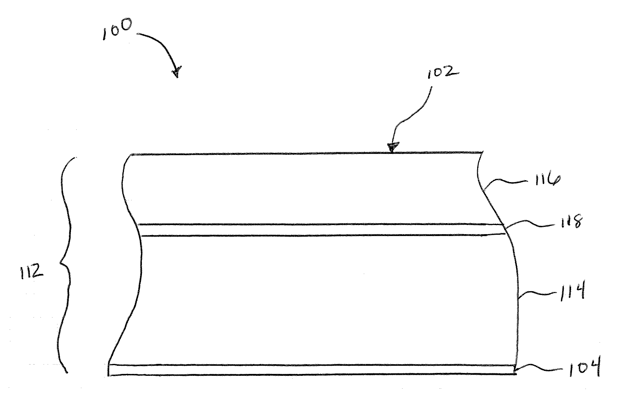
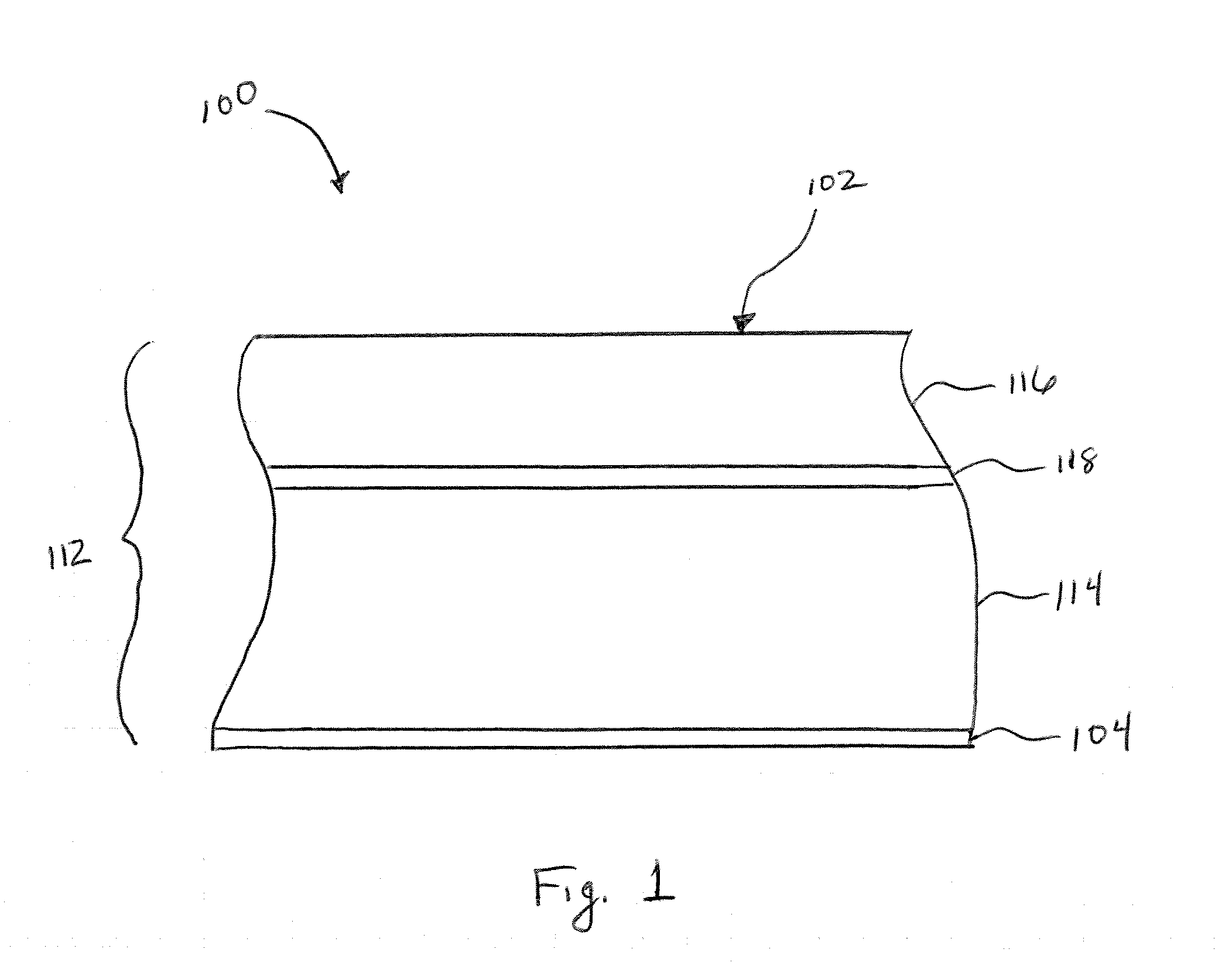
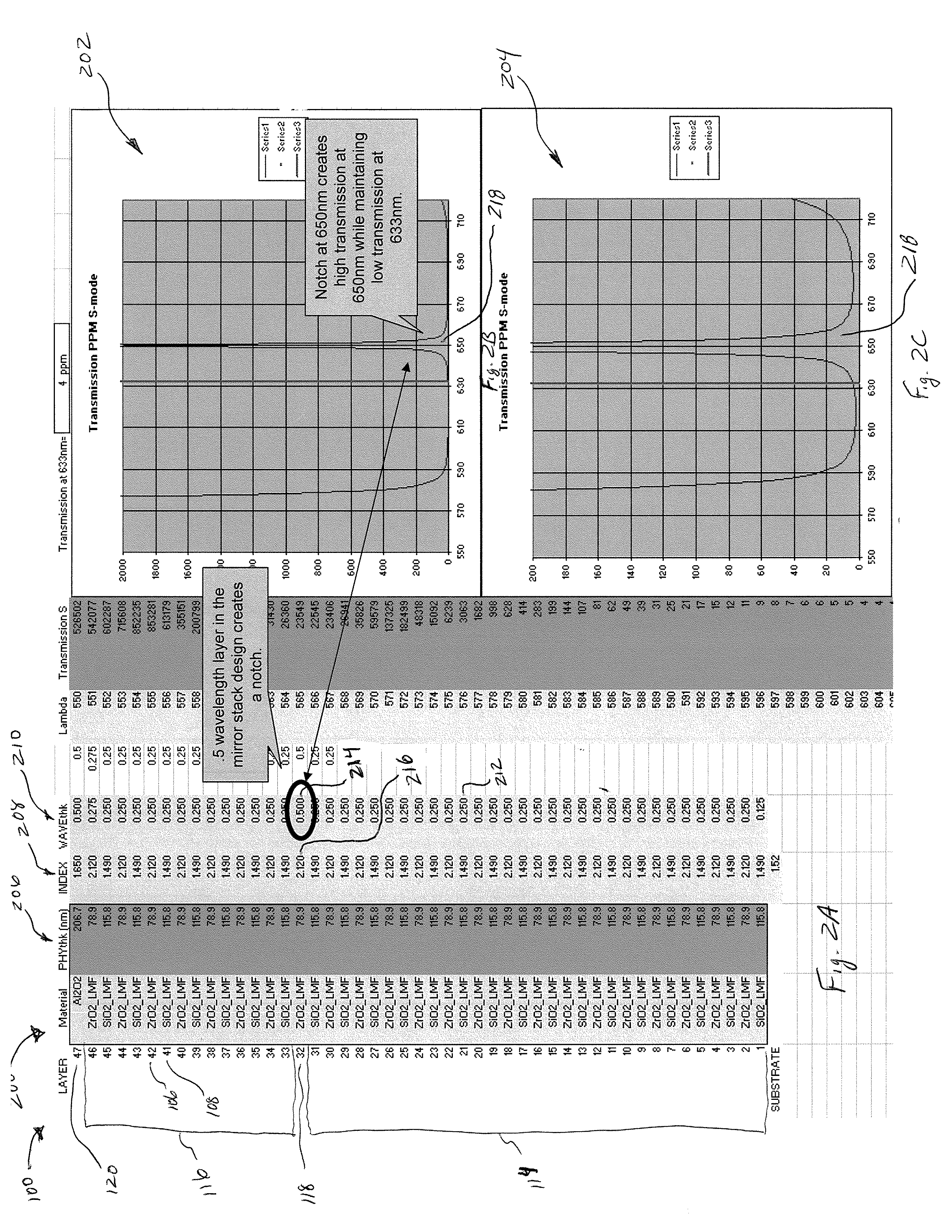
[0013]The following description generally relates to a type of laser mirror having an intermediate substance, such as a thicker optical coating, positioned within approximately a mid portion of the laser mirror for improving the performance of an RLG and specifically for improving the reflectance of at least a predetermined wavelength emission. The properties of the intermediate substance and its placement within the laser mirror results in the laser mirror sufficiently reflecting a first predetermined laser emission wavelength at or near 633 nanometers while ...


PUM


Abstract

A laser mirror for a ring laser gyroscope (RLG) includes an intermediate optical coating, positioned within approximately a mid portion of the laser mirror for improving the performance of the RLG, and specifically for improving the reflectance of at least one wavelength emission. The properties of the intermediate optical coating and its placement within the laser mirror results in a good reflection of a first predetermined wavelength emission wavelength, for example a 633 nanometer wavelength emission, and a poor reflection of a second predetermined wavelength emission, for example a 650 nanometer wavelength emission. In one embodiment, the intermediate optical coating includes a half-wave or a multiple half-wave thickness and is made from Zirconium Oxide.

Description

BACKGROUND OF THE INVENTION[0001]A ring laser gyroscope (RLG) is a device that measures angular rate by optical means. Two counter-rotating laser beams, formed within a resonate cavity, are detected and provide an accurate measure of angular rate. A typical laser gyroscope has a laser emission wavelength of 633 nanometers. A key component in this device is the quality of the laser mirrors or reflectors.[0002]The laser mirrors used in ring laser gyroscope applications are commonly referred to as multilayer dielectric coated mirrors or multilayer high-reflectance coated mirrors. These mirrors are made by depositing, in an alternating manner, optical coatings that have different indices of refraction, preferably one optical coating has a high index of refraction material and the other optical coating has a low index of refraction.[0003]As improvements have been made with the reflectance of these mirrors, a second laser emission wavelength of 650 nanometers has developed. The 650 nanome...

Claims


Application Information

Patent Timeline
Patent Type & Authority Applications(United States)
IPC IPC(8): H01S3/083
CPCG01C19/661G02B5/0833H01S3/083H01S3/08059G02B5/285
Inventor ANDERSON, CARL DAVIDRAMBERG, RANDY J.
Owner HONEYWELL INT INC
Why Eureka
Eureka Blog
Learn More