Method and system for estimating and compensating non-linear distortion in a transmitter using data signal feedback

a nonlinear distortion and data signal technology, applied in the field of wireless communication, can solve the problems of limiting the performance of integrated pa circuitry, affecting the range of input power levels, and power amplifier circuits that may distort output signals

Inactive Publication Date: 2008-06-12
AVAGO TECH WIRELESS IP SINGAPORE PTE
View PDF5 Cites 51 Cited by
  • Summary
  • Abstract
  • Description
  • Claims
  • Application Information

AI Technical Summary

Benefits of technology

[0016]A method and system for estimating and compensating for non-linear distortion in a transmitter using data signal feedback, su

Problems solved by technology

Because of these large swings in output power levels, power amplifier (PA) circuits may distort the output signal.
Distortion, however, is a characteristic, which may be observed in PA circuits that are utilized across a wide range of applications, and may not be limited to PA circuits utilized in wireless systems.
Whereas the pressing need to increase the integration of functions performed within a single IC, and attendant increase in the number of semiconductor devices, may push semiconductor fabrication technologies toward increasingly shrinking semiconductor device geometries, these very semiconductor fabrication technologies may impose limitations on the performance of the integrated PA circuitry.
For example, utilizing a 65 nm CMOS process may restrict the range of input power levels for which the PA provides linear output power level amplification.
Furthermore, AM-PM distortion may also vary as a function of the input signal power level.
The AM-AM distortion and/or the AM-PM distortion comprise transmitter impair

Method used


Image

  • Method and system for estimating and compensating non-linear distortion in a transmitter using data signal feedback
  • Method and system for estimating and compensating non-linear distortion in a transmitter using data signal feedback
  • Method and system for estimating and compensating non-linear distortion in a transmitter using data signal feedback

Examples


Embodiment Construction

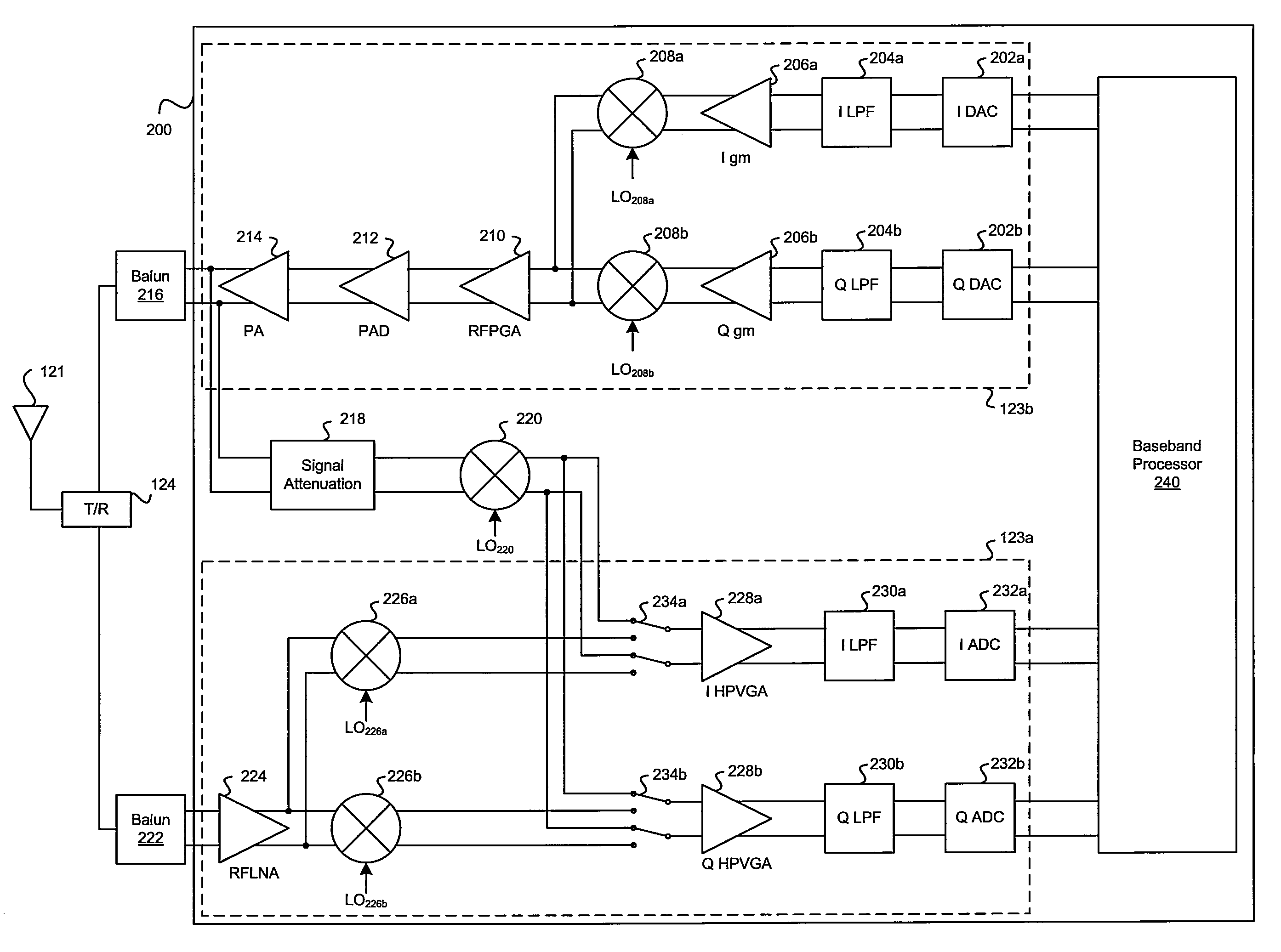
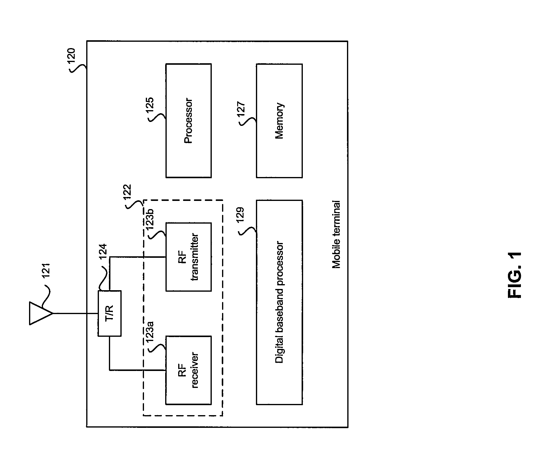
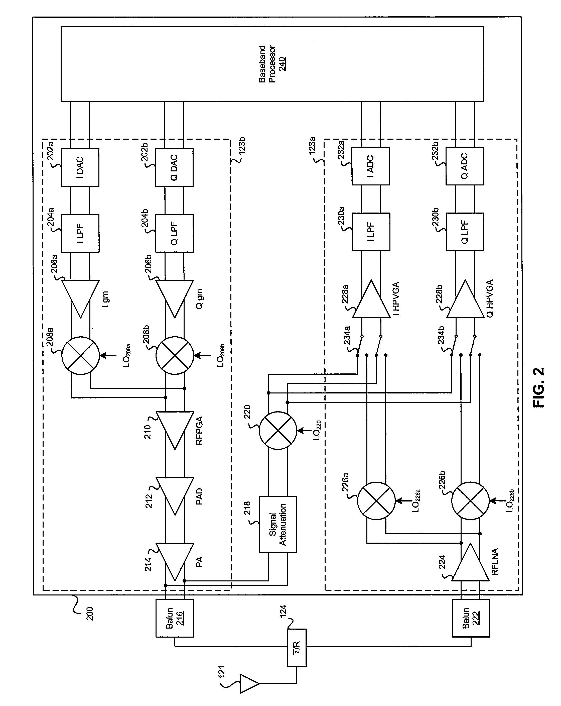
[0033]Certain embodiments of the invention may be found in a method and system for estimating and compensating for non-linear distortion in a transmitter using data signal feedback. Various embodiments of the invention may comprise a method and system by which predistortion values, for compensating for non-linear distortion, may be computed based on feedback signals generated in response to wideband input signals. The wideband input signals may comprise a plurality of frequency components and / or signal amplitudes. In an exemplary embodiment of the invention, the wideband input signal may be an orthogonal frequency division multiplexing (OFDM) signal comprising a plurality of data symbols modulated by a plurality of frequency carrier signals spanning a range of frequencies. In another exemplary embodiment of the invention, the wideband signal may be a training signal, which comprises a range of frequency signals to meet spectral density requirements under applicable standards. The pr...


PUM


Abstract

Aspects of a method and system for estimating and compensating for non-linear distortion in a transmitter using data signal feedback are presented. Aspects of the system may include a method and system by which predistortion values, for compensating for non-linear distortion, may be computed based on feedback signals generated in response to wideband input signals. The wideband input signals may comprise a plurality of frequency components and/or signal amplitudes. The predistortion values may be computed by time-synchronizing a wideband input signal generated at a given time instant, and the feedback signal generated at a subsequent time instant in response. A predistortion function may be computed by computing predistortion values for a plurality of signal amplitude values and/or IC operating temperatures. The computed values may be stored in a lookup table and retrieved to predistort subsequent wideband input signals based on the amplitude of the signals and/or the IC operating temperature.

Description

CROSS-REFERENCE TO RELATED APPLICATIONS / INCORPORATION BY REFERENCE[0001]This application makes reference to, claims priority to, and claims the benefit of U.S. Provisional Application Ser. No. 60 / 868,818, filed on Dec. 6, 2006.[0002]This application makes reference to U.S. application Ser. No. 11 / 618,876, filed on Dec. 31, 2006.[0003]Each of the above stated applications is hereby incorporated herein by reference in its entirety.FIELD OF THE INVENTION[0004]Certain embodiments of the invention relate to wireless communications. More specifically, certain embodiments of the invention relate to a method and system for estimating and compensating for non-linear distortion in a transmitter using data signal feedback.BACKGROUND OF THE INVENTION[0005]A power amplification circuit in a wireless system is typically a large signal device. In wireless local area network (WLAN) systems, the power amplifier circuit may transmit output signals at average power levels in the range of 10 dBm to 15 ...

Claims


Application Information

Patent Timeline
IPC IPC(8): H04B1/04
CPCH03F1/3247H03F1/3294H03F1/34H03F3/24H03F2200/336H04B2001/0425H03F2200/438H03F2200/447H03F2200/468H03F2201/3233H04B1/0475H03F2200/408H03F1/3241
Inventor VARGHESE, GEORGESAXENA, PANKAJKARANAM, SREENIVASBELLARY, SUDHINDRA
Owner AVAGO TECH WIRELESS IP SINGAPORE PTE
Why Eureka
Try Eureka