Buckle for a safety belt

a safety belt and seat belt technology, applied in the field of seat belt buckles for seat belts, can solve the problems of comparatively expensive components of hall sensors and microswitches, and achieve the effect of high mechanical strength

Inactive Publication Date: 2008-06-19
ROLF PRETTL
View PDF11 Cites 10 Cited by
  • Summary
  • Abstract
  • Description
  • Claims
  • Application Information

AI Technical Summary

Benefits of technology

The patent describes a device that allows force to be transmitted from a seat belt tongue to a snap-action plate in a simple and strong way. The device also has a rotating shaft that is connected to a lever, which is used to insert the seat belt tongue. This design provides a more efficient and reliable connection between the seat belt and the vehicle's safety system.

Problems solved by technology

The technical problem addressed in this patent is to provide a seat belt buckle with a sensor device that can electrically sense whether the seat belt tongue is locked, without using expensive and potentially unreliable components such as Hall sensors or microswitches.

Method used


Image

  • Buckle for a safety belt
  • Buckle for a safety belt
  • Buckle for a safety belt

Examples


Embodiment Construction

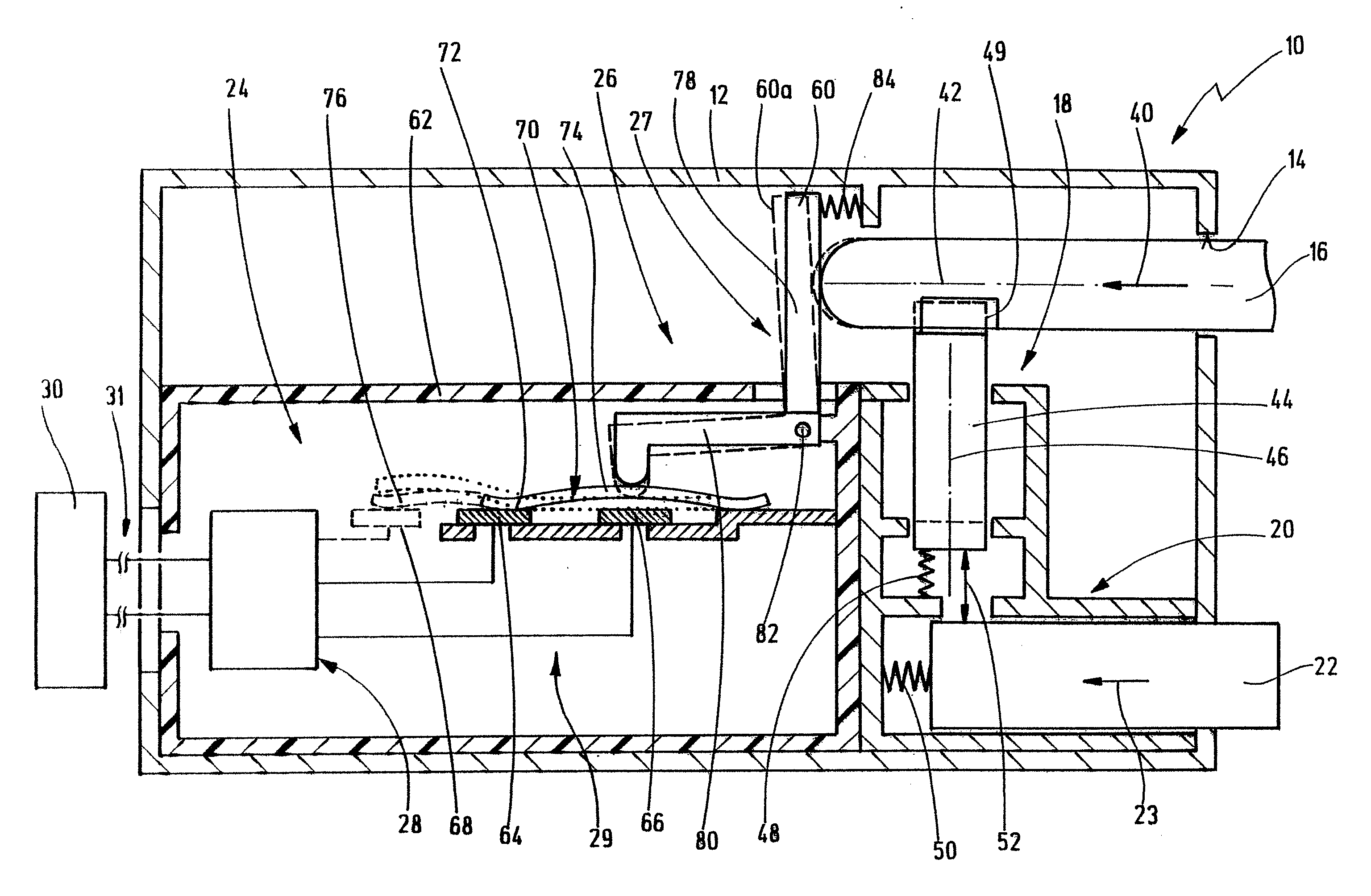
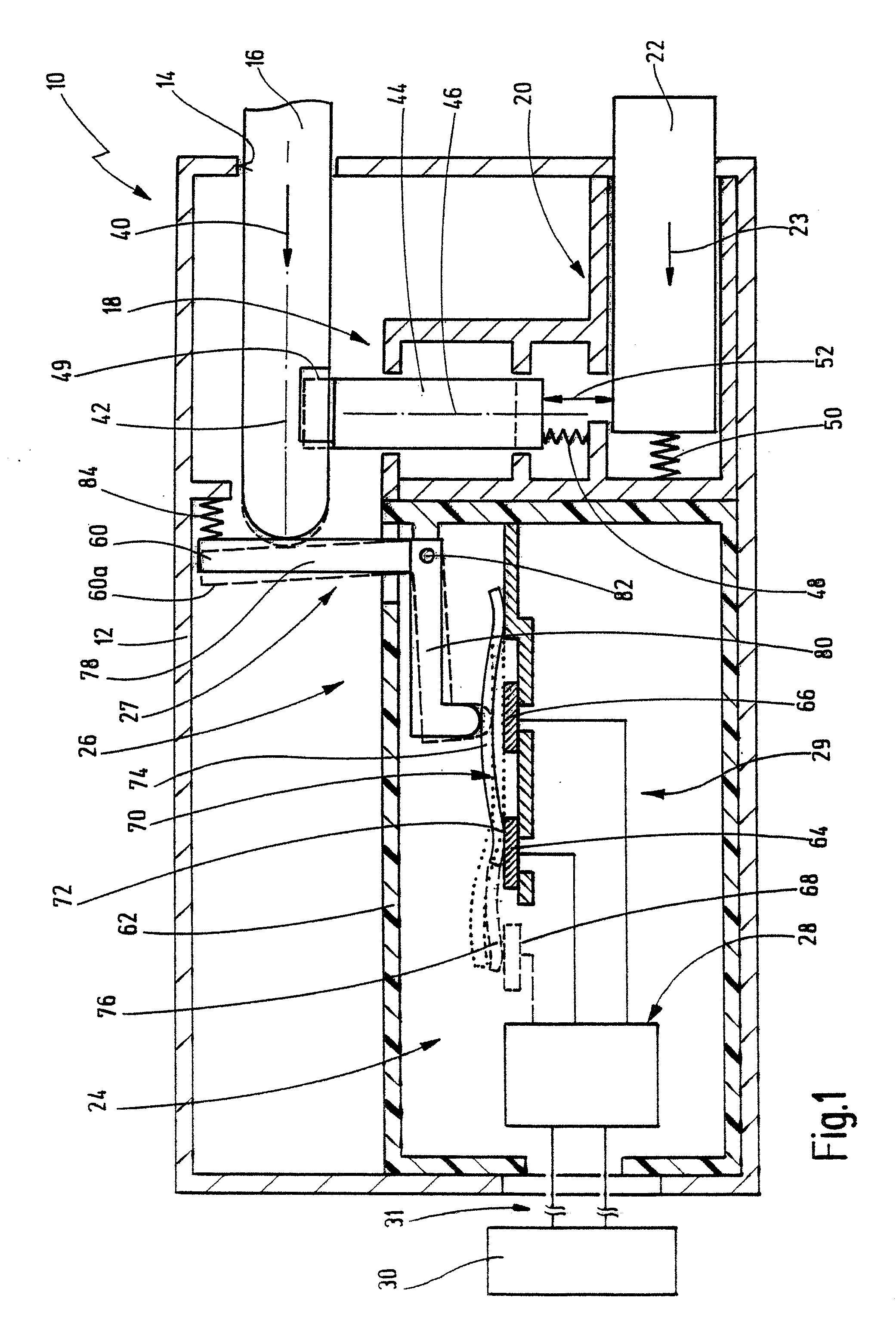
[0054]In FIG. 1, a first embodiment of a seat belt buckle according to the invention is generally designated by 10.

[0055]The seat belt buckle 10 serves as a seat belt buckle for a seat belt in a motor vehicle and has a housing 12.

[0056]An opening 14 for the insertion of a seat belt tongue 16 is formed on the housing 12. In addition, a locking device 18 is provided in the housing 12 in order to lock the seat belt tongue 16 (to close the seat belt).

[0057]Finally, a release device 20 is provided in the housing 12 in order to release the locked arrangement of the seat belt tongue 16 again (in order to take off the seat belt). The release device 20 has a pushbutton key 22 which is activated in order to release the locked arrangement of the seat belt tongue 16, as is indicated schematically at 23.

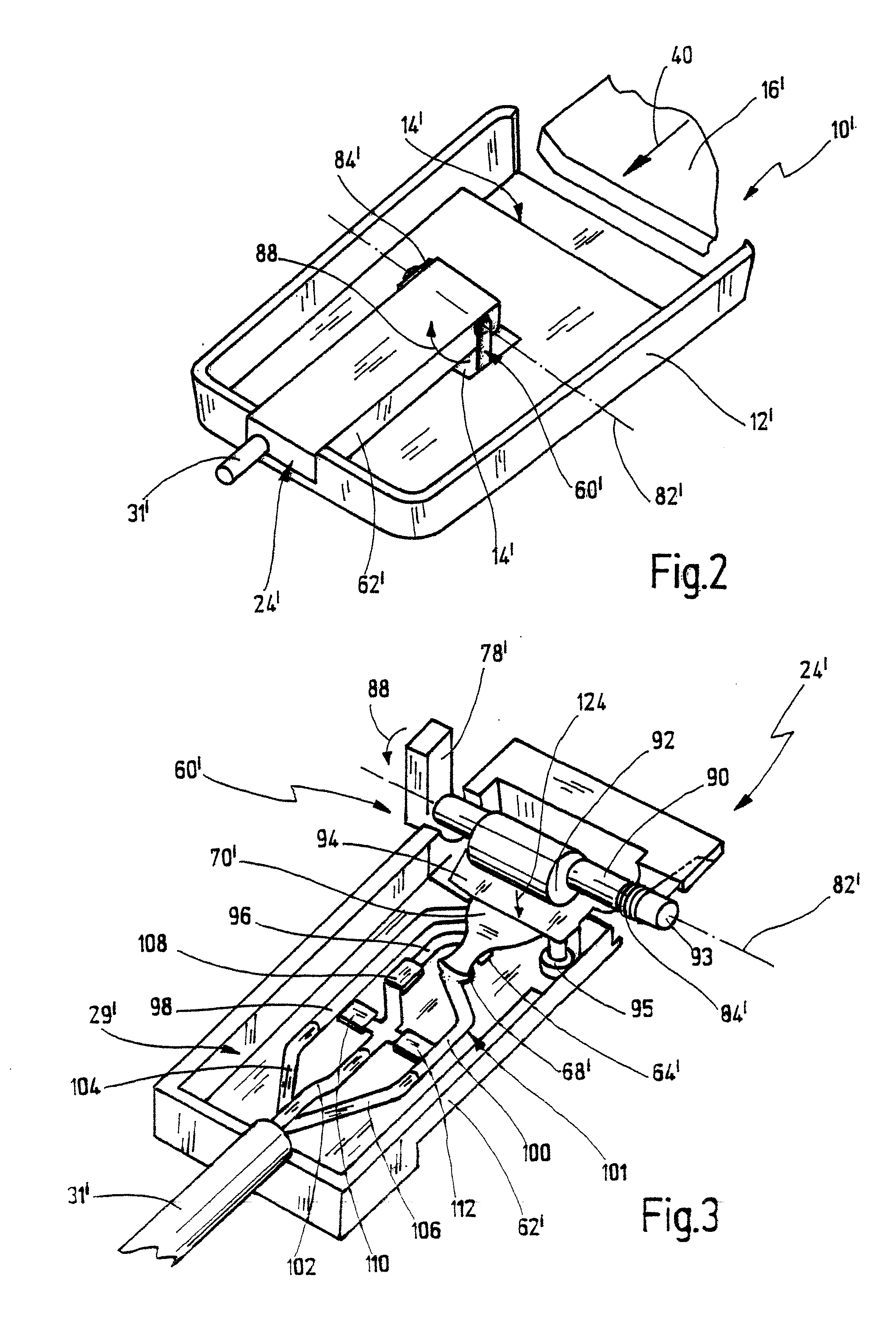
[0058]In addition, the seat belt buckle 10 has a sensor device 24 for electrically sensing whether the seat belt tongue 16 is locked.

[0059]The sensor device 24 has an electrical switch arrangemen...


PUM


Abstract

A seat belt buckle for seat belts has a housing, an opening for inserting a seat belt tongue, a locking device for locking the seat belt tongue, and a release device for releasing the seat belt tongue from the lock. A sensor device electrically senses whether the seat belt tongue is locked, wherein the sensor device has a switch arrangement which can be activated by the seat belt tongue. The switch arrangement has an electrically conductive snap-action plate that can be moved between a first switched position and a second switched position. A mechanical activation device transmits a force exerted on the seat belt tongue during the insertion of the seat belt tongue onto the snap-action plate in order to move the snap-action plate from the first switched position into the second switched position. As a result, an electrical contact element is closed or opened.

Description


Claims


Application Information

Patent Timeline
Owner ROLF PRETTL
Why Eureka
Try Eureka