Hydraulic control system having an upper depth stop valve with bypass

a control system and stop valve technology, applied in the field of agricultural implements, can solve the problems of limiting the maximum raised height of the planter from the ground, limiting the maximum height of the road transport position, and the drawbacks of the known hydraulic system, and achieve the effect of simple design of the hydraulic control system of the invention

Inactive Publication Date: 2008-06-19
CNH IND CANADA
View PDF21 Cites 3 Cited by
  • Summary
  • Abstract
  • Description
  • Claims
  • Application Information

AI Technical Summary

Benefits of technology

[0011]The present invention provides a hydraulic control system, an agricultural implement and a method of moving an agricultural frame that addresses the drawbacks described above. The hydraulic control system of the invention includes an upper depth stop valve with a bypass allowing for controlled movement between field transport and road transport positions. The hydraulic control system of the invention is also simple in design and parts for ready manufacturability.

Problems solved by technology

However, known hydraulic systems have drawbacks.
This is due to the fact that when an operator strokes a master cylinder controlling the height of the implement, the cylinders typically bottom out thereby limiting the maximum raised height of the planter from the ground.
The limited maximum height of the road transport position has proved problematic when the planter needs to be moved long distances over ditches and other uneven surfaces.
Portions of the planter may not have adequate clearance to cross these uneven surfaces.
Likewise, the height (clearance of the implement frame from the ground) of the field transport position in many of these systems is unnecessarily high.
Even in those systems that can achieve different road transport and field transport heights, there is not an adequate system to control the movement of the implement from the field transport to the road transport position.
In many systems there is not an adequate upper stop.
Furthermore, it is often unnecessary and time consuming to raise the tool frame to a fully raised position during planting operations.
This system, while somewhat satisfactory for its intended purpose, exhibits drawbacks as the electronic upper depth stop system is overly complex and costly to manufacture.

Method used


Image

  • Hydraulic control system having an upper depth stop valve with bypass
  • Hydraulic control system having an upper depth stop valve with bypass
  • Hydraulic control system having an upper depth stop valve with bypass

Examples


Embodiment Construction

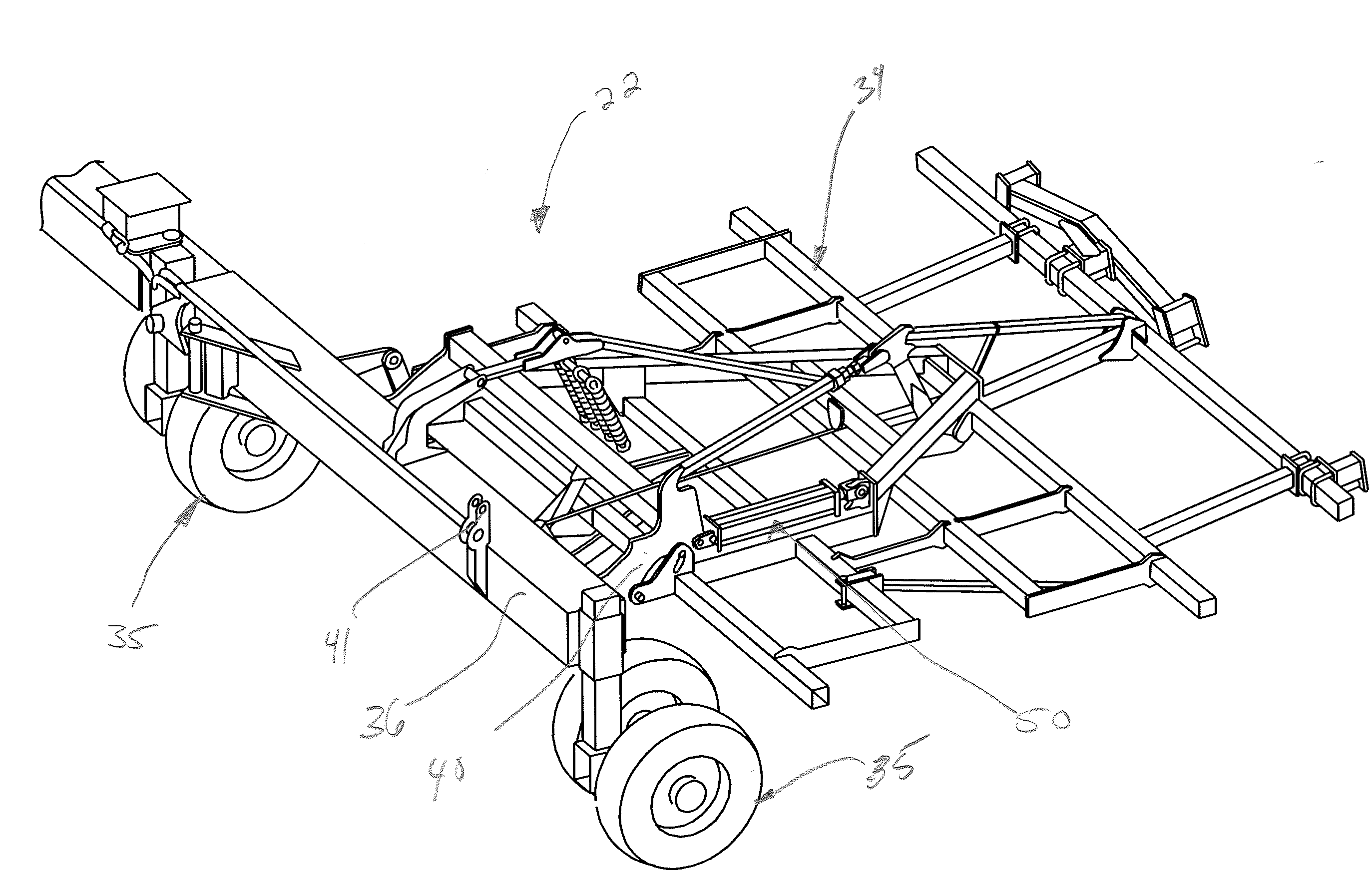
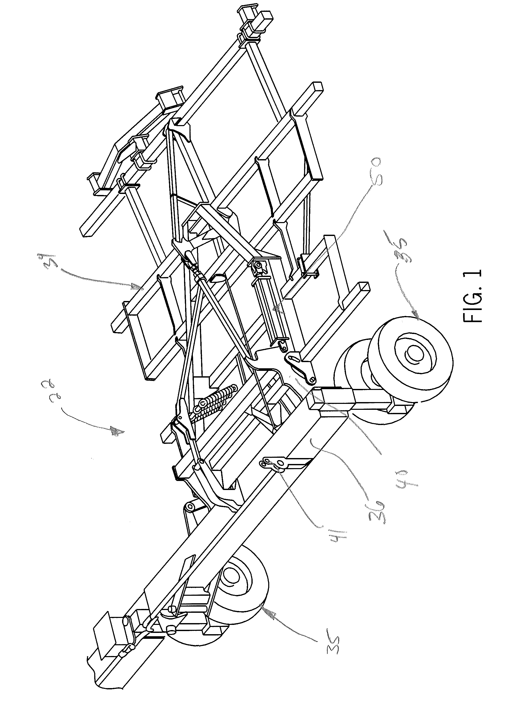
[0028]In accordance with the present invention, an agricultural implement 22 is provided to be conveyed by a self propelled vehicle such as a tractor, combine or similar vehicle capable of use in an agricultural field. The agricultural implement may be attached to the vehicle in any of a variety of different manners. For example, the agricultural implement 22 may be securely mounted to either the front or rear of the vehicle chassis so as to be carried by the vehicle. Alternatively, and as embodied herein for purpose of illustration and not limitation, the agricultural implement may be attached to the vehicle by a one-point, two-point or three-point hitch assembly.

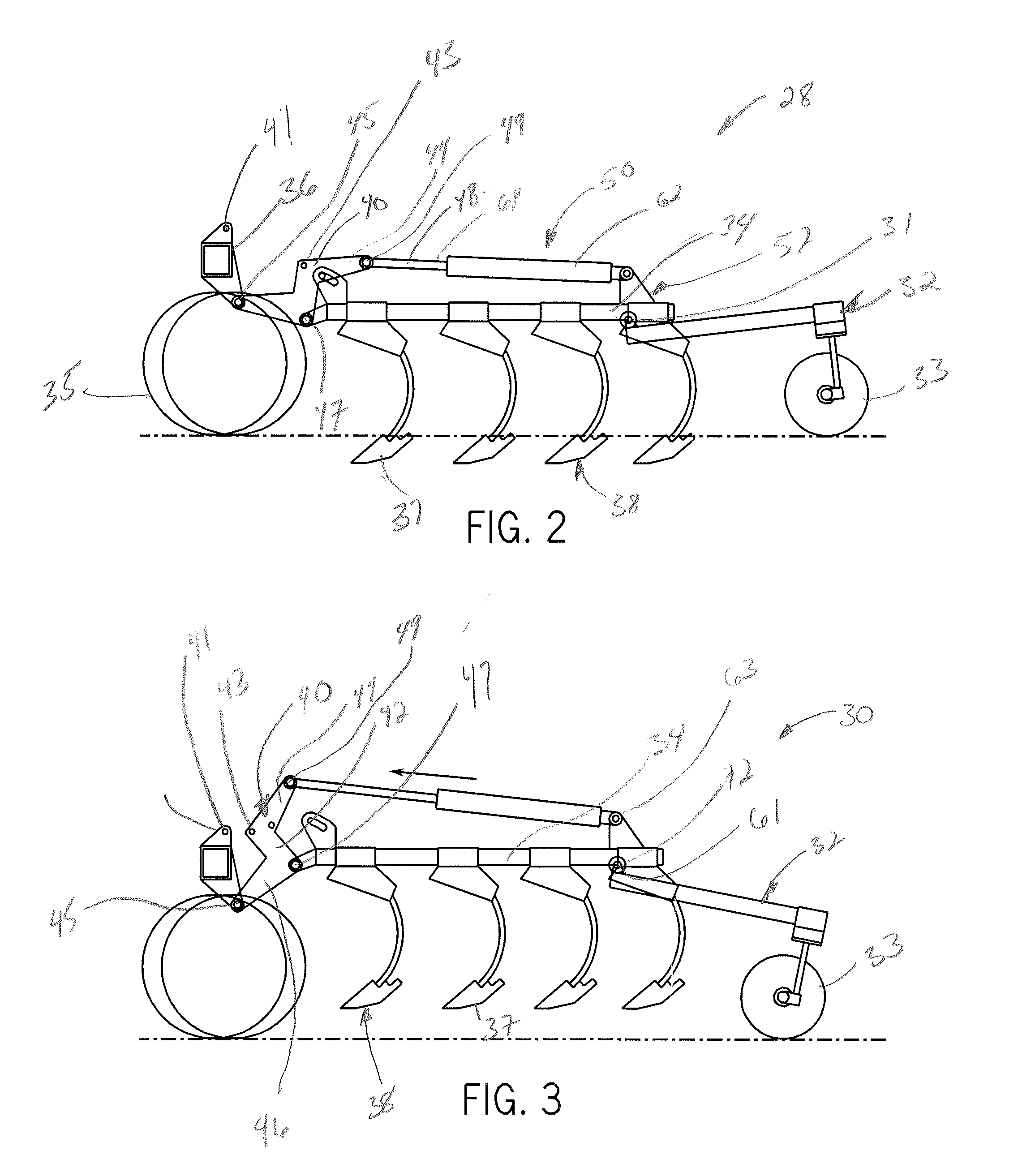
[0029]FIG. 7 illustrates a hydraulic control system 20 in accordance with the present invention in combination with an agricultural implement 22. The hydraulic control system 20 is generally configured to arrange an implement frame or implement tool frame 34 of the agricultural implement 22 (illustrated in FIGS. 1-6) in al...


PUM


Abstract

A hydraulic control system for use with a farm implement is configured to move an implement frame between a first height corresponding to a planting position, a second height corresponding to a field transport position, a third height corresponding to a lock up position and a fourth height corresponding to a road transport position. At least one hydraulic cylinder is mounted to a rock shaft connected to the implement frame to move the implement frame between the first height, the second, the third height and the fourth height. At least one depth stop valve is in communication with the hydraulic cylinder. The depth stop valve includes a bypass configured to allow controlled movement of the hydraulic cylinder between the second position and the third positions.

Description

BACKGROUND OF THE INVENTION[0001]1. Field of the Invention[0002]The present invention relates generally to agricultural implements such as agricultural planters. More particularly, the present invention relates to an agricultural implement having at least one ground engaging tool supported on an implement frame and a fluid circuit to control movement of the implement frame between working and transport positions. Even more particularly, the present invention is directed to a fluid control circuit for controlling movement of the implement frame, having an upper depth stop valve with a bypass in communication with a hydraulic cylinder to allow controlled upward movement of the tool frame between a field transport position and a road transport position.[0003]2. Discussion of the Related Art[0004]Conventional planters typically include a series of evenly spaced row planter units connected to an implement frame and / or tool bar so as to be towed across a field. The row planter units are g...

Claims


Application Information

Patent Timeline
Patent Type & Authority Applications(United States)
IPC IPC(8): A01B63/00
CPCA01B63/32
Inventor FRIGGSTAD, TERRANCE A.MAYERLE, DEAN J.
Owner CNH IND CANADA
Why Eureka
Try Eureka