Hydraulic control device and hydraulic control method for automatic transmission

a hydraulic control device and automatic transmission technology, applied in mechanical equipment, propulsion parts, transportation and packaging, etc., can solve the problems of motor torque overshoot, belt slipping or clutch slipping, and increase the input torque of a continuously variable transmission belt type, so as to simplify the control logic on the transmission hydraulic control sid

Active Publication Date: 2022-08-23
JATCO LTD +1
View PDF6 Cites 0 Cited by
  • Summary
  • Abstract
  • Description
  • Claims
  • Application Information

AI Technical Summary

Benefits of technology

[0010]Consequently, the control logic on the transmission hydraulic control side can be simplified when the coordination control of the transmission hydraulic control and the torque assist control by the assist motor is carried out.

Problems solved by technology

In this torque assist control, if the control that increases driving source torque by an assist motor torque is carried out, input torque to a belt type continuously variable transmission is increased, and belt slipping or clutch slipping might occur.
If the belt slipping or clutch slipping occurs, there is possibility that motor torque overshoot occurs when the assist motor torque is switched to the engine torque.
Consequently, there is a problem that, even in a switching state of the same motor torque and engine torque, if the number of types of the torque assist is increased, since the number of switching patterns of the torque assist levels which has to be considered is increased, control logic becomes complicated.

Method used


Image

  • Hydraulic control device and hydraulic control method for automatic transmission
  • Hydraulic control device and hydraulic control method for automatic transmission
  • Hydraulic control device and hydraulic control method for automatic transmission

Examples


Embodiment Construction

[0021]In the following, a mode for implementing a hydraulic control device for an automatic transmission of the present invention will be explained based on an embodiment shown in the drawings.

[0022]The control device in the embodiment is one applied to an engine vehicle equipped with an assist motor which mounts a belt type continuously variable transmission (an example of an automatic transmission) composed of a torque converter, a forward / reverse switching mechanism, a variator and a final reduction gear mechanism. In the following, the configuration of the embodiment will be explained by dividing it into “entire system configuration”, “details of configuration of coordination control system” and “torque assist coordination control processing configuration”.

[0023][Entire System Configuration]

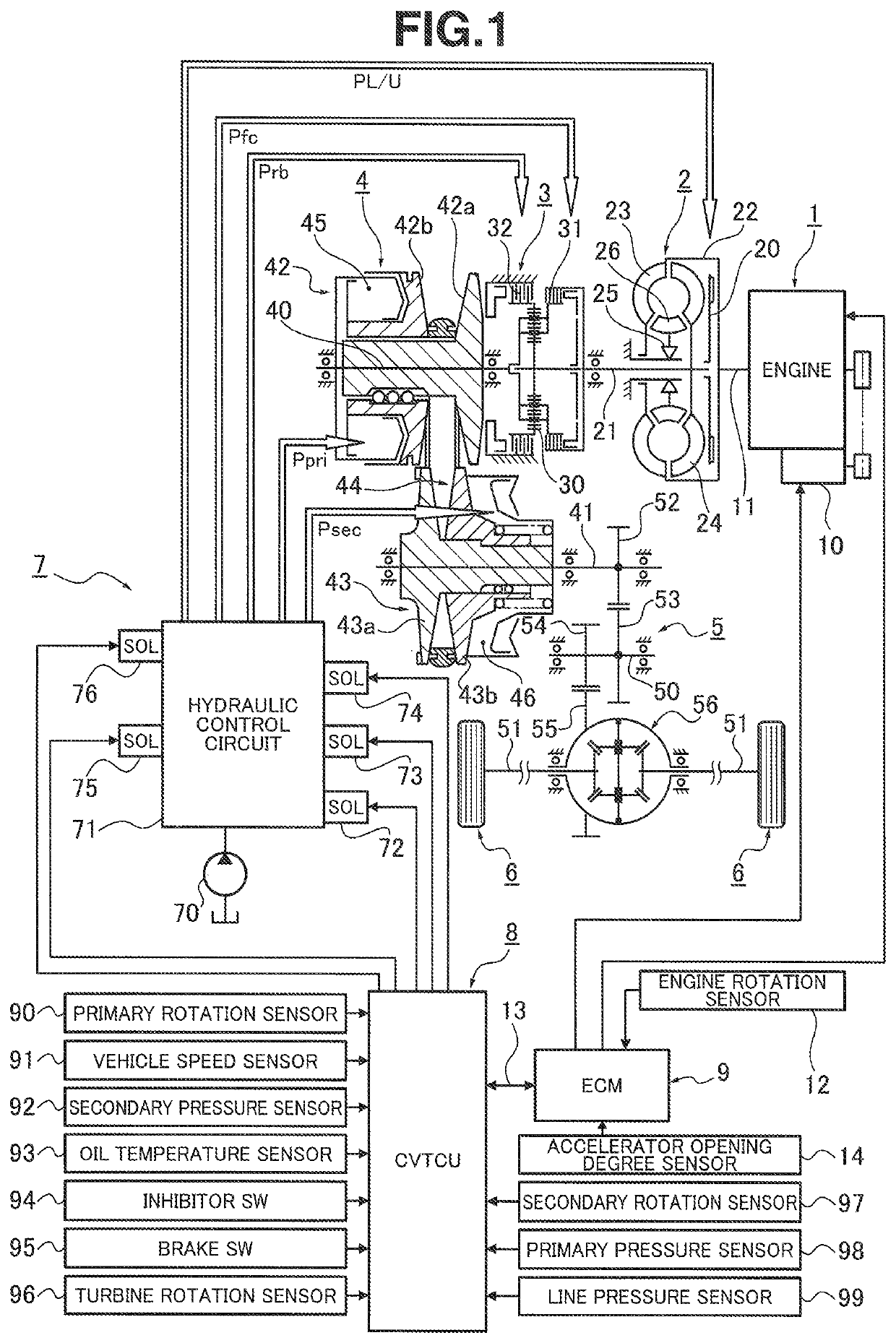
[0024]FIG. 1 shows a control system and a driving system of an engine vehicle to which the control device for a belt type continuously variable transmission of the embodiment is applied. In t...


PUM


Abstract

As a driving source, an engine and an assist motor are provided. An engine control module includes a torque assist control unit for controlling the assist motor by a plurality of types of switching patterns having different torque assist levels. A CVT control unit includes a torque assist coordination control unit that, when a torque assist request is input from the torque assist control unit, carries out the control that increases commanded hydraulic pressure so as to increase the hydraulic pressure of hydraulically operated members. When carrying out the control that increases the commanded hydraulic pressure, the torque assist coordination control unit unifies the levels of the commanded hydraulic pressure regardless of the types of the switching patterns.

Description

TECHNICAL FIELD[0001]The present invention relates to a hydraulic control device and a hydraulic control method for an automatic transmission to be mounted on a vehicle.BACKGROUND TECHNOLOGY[0002]Heretofore, there has been know a control device and its control method for a hybrid vehicle in which when the assisting of a motor assist is carried out, before motor torque is increased, secondary pulley pressure (line pressure) is increased to increase the transmission torque capacity of a continuously variable transmission (see, for example, a patent document 1).[0003]However, in the above conventional technique, one type of a motor assist is carried out, and hydraulic control for carrying out two types of small and large assists is not disclosed. In a case where two types of the motor assists are carried out, as patterns for increasing motor torque, three types of patterns of zero→small, zero→large and small→large must be considered, and consequently, control logic becomes complicated....

Claims


Application Information

Patent Timeline
Patent Type & Authority Patents(United States)
IPC IPC(8): B60W10/08F16H61/02B60K6/485B60K6/543F16H59/74
CPCF16H61/02B60W10/08B60K6/485B60K6/543B60W2710/083F16H59/74B60W10/107B60W2710/1077B60K6/48F16H61/0021F16H61/30F16H2061/2823F16H61/662B60Y2200/92F16H61/66272Y02T10/72Y02T10/62
Inventor HIRATA, SHOICHIMIYAISHI, HIRONORI
Owner JATCO LTD
Why Eureka
Try Eureka