Engine having continuously variable valve timing mechanism

a timing mechanism and valve technology, applied in valve arrangements, machines/engines, mechanical equipment, etc., can solve the problems of long and complicated flow circuits for controlling hydraulic pressure, and achieve the effects of reducing space requirements, reducing fuel consumption, and minimizing compression loss

Active Publication Date: 2015-10-27
HYUNDAI MOTOR CO LTD +1
View PDF10 Cites 0 Cited by
  • Summary
  • Abstract
  • Description
  • Claims
  • Application Information

AI Technical Summary

Benefits of technology

[0014]Various aspects of the present invention are directed to providing an engine having a continuously variable valve timing mechanism having advantages of minimizing a compression loss in a combustion chamber and reducing fuel consumption. According to an exemplary embodiment of the present invention, an object of the present invention is to provide an engine having the variable valve timing mechanism which can reduce spaces required for mounting an oil control valve and a solenoid valve, simplify a flow circuit required for hydraulic control, and reduce a length of the flow circuit.
[0022]To achieve the object of the present invention, an engine having a variable valve timing mechanism can reduce an overall mounting space, simplify hydraulic control circuits, and reduce a length of the circuits by forming the oil control valve in the variable valve bolt, and mounting the solenoid valve to an outer side of the variable rotation unit.

Problems solved by technology

Along with this, a space for mounting the oil control valve 130 and the solenoid valve is required, and a flow circuit for controlling a hydraulic pressure is liable to be lengthy and complicate.

Method used


Image

  • Engine having continuously variable valve timing mechanism
  • Engine having continuously variable valve timing mechanism
  • Engine having continuously variable valve timing mechanism

Examples


Embodiment Construction

[0029]Reference will now be made in detail to various embodiments of the present invention(s), examples of which are illustrated in the accompanying drawings and described below. While the invention(s) will be described in conjunction with exemplary embodiments, it will be understood that the present description is not intended to limit the invention(s) to those exemplary embodiments. On the contrary, the invention(s) is / are intended to cover not only the exemplary embodiments, but also various alternatives, modifications, equivalents and other embodiments, which may be included within the spirit and scope of the invention as defined by the appended claims.

[0030]An exemplary embodiment of the present invention will hereinafter be described in detail with reference to the accompanying drawings.

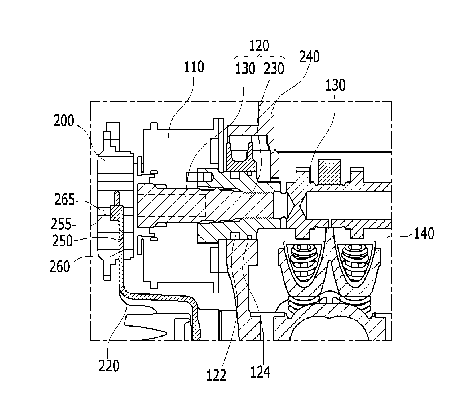
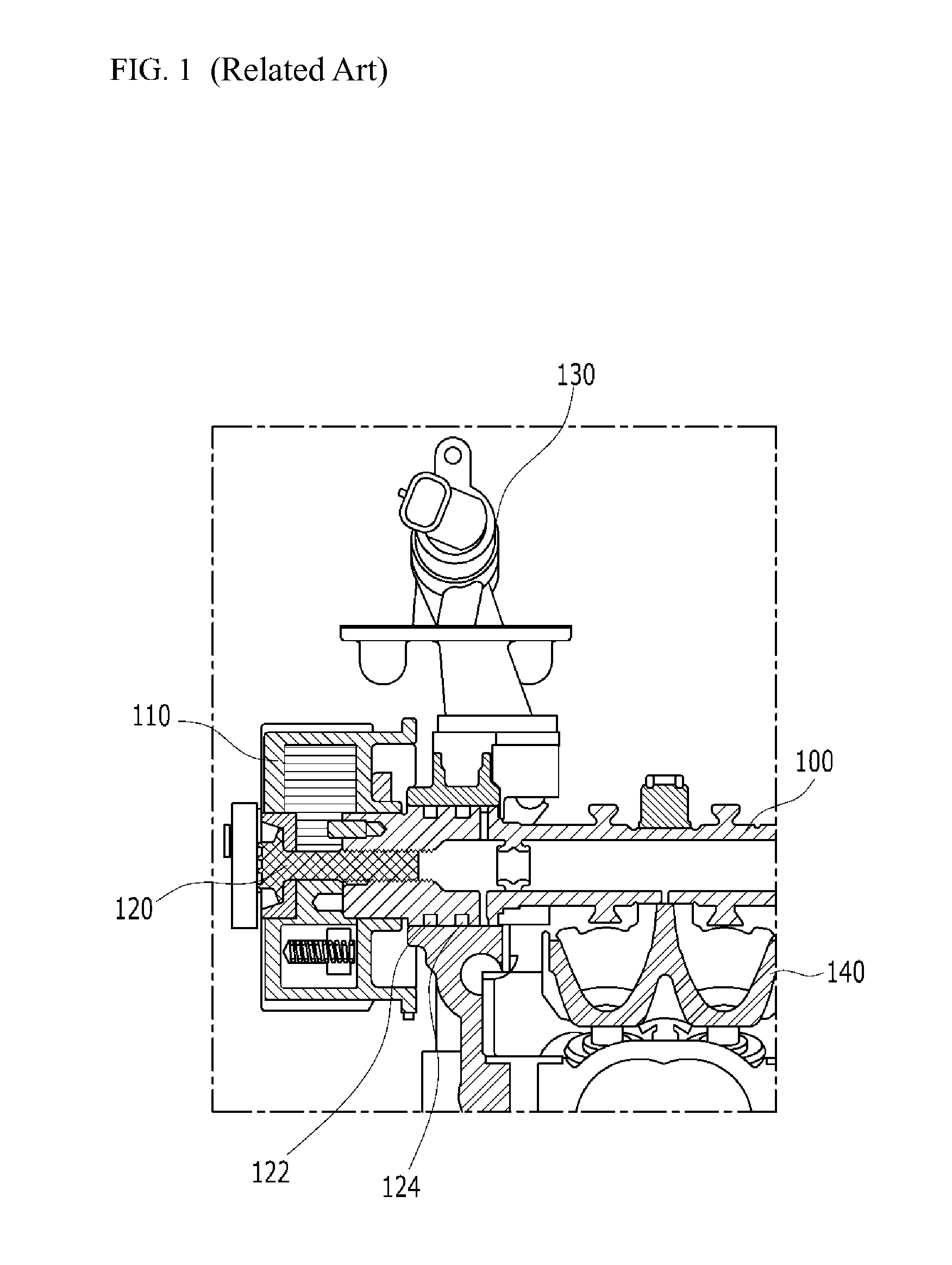
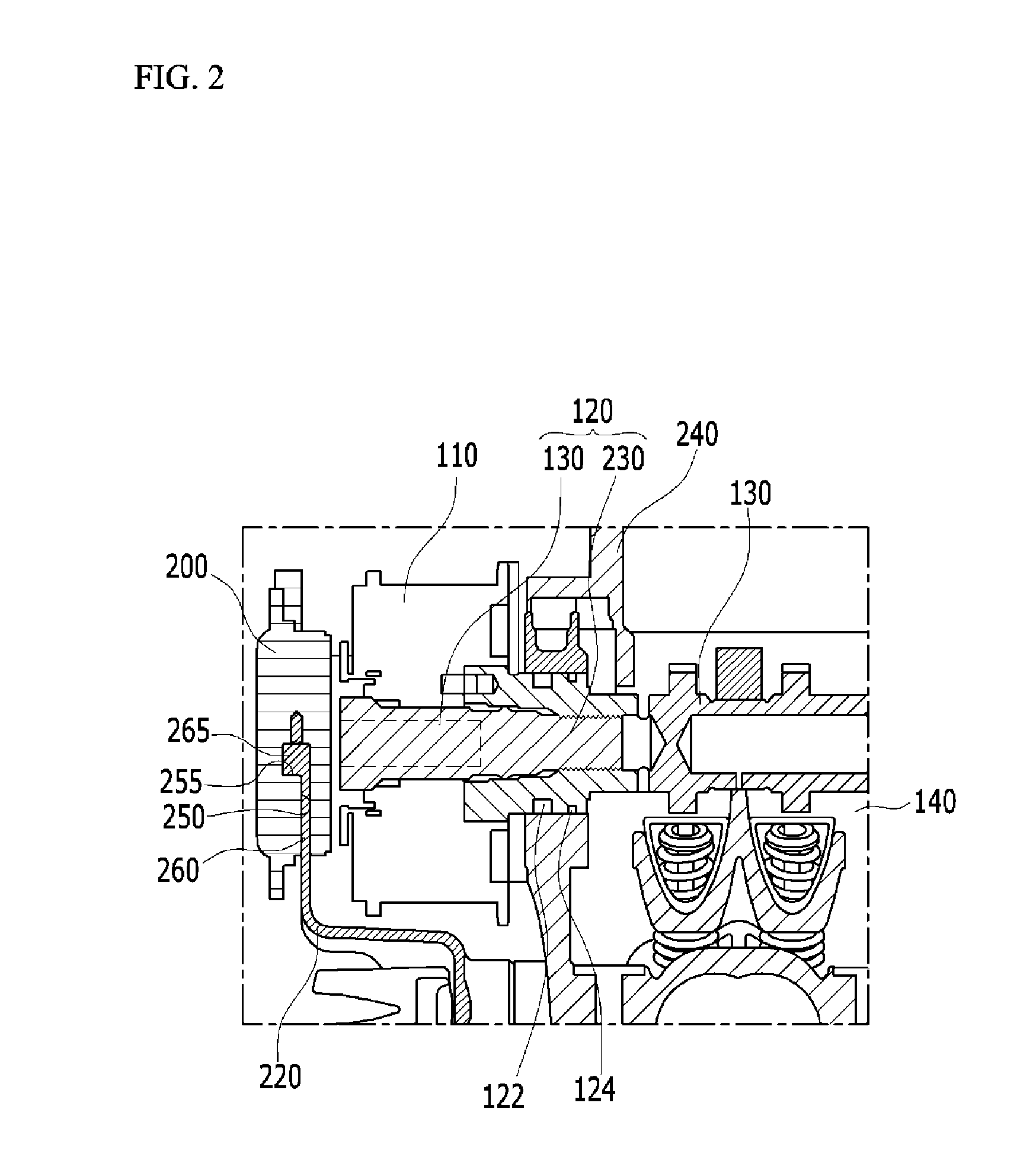
[0031]An engine to which the present invention is applicable is a gasoline or diesel internal combustion engine to which MPI(Multi Point Injection), GDI(Gasoline Direct Injection), TGDI(Turbo G...


PUM


Abstract

An engine having a variable valve timing mechanism may include a camshaft having a cam formed thereon for moving an intake or exhaust valve, a variable rotation unit disposed on the same axis with the camshaft to rotate the camshaft to have a retard angle chamber and an advance angle chamber for controlling a retard angle and an advance angle of the camshaft, a variable valve bolt having a fastening portion for fastening the variable rotation unit to the camshaft, and an oil control valve for making selective supply of hydraulic oil to the retard angle chamber and the advance angle chamber, and a valve controller disposed on an outer side of the variable rotation unit for controlling the oil control valve in the variable valve bolt.

Description

CROSS-REFERENCE TO RELATED APPLICATION[0001]The present application claims priority to Korean Patent Application No. 10-2013-0107414 filed on Sep. 6, 2013, the entire contents of which is incorporated herein for all purposes by this reference.BACKGROUND OF THE INVENTION[0002]1. Field of the Invention[0003]The present invention relates to an engine having a continuously variable valve timing mechanism which makes a camshaft which moves an intake or exhaust valve to retard or advance for minimizing a compression loss in a combustion chamber and reducing fuel consumption.[0004]2. Description of Related Art[0005]In order to improve an engine performance, reduce the fuel consumption, and improve a quality of exhaust gas, the continuously variable valve timing (CVVT) mechanism has been introduced for making a rotation phase of the camshaft to advance or retard.[0006]FIG. 1 illustrates a schematic diagram of an engine having a related art continuously variable valve timing mechanism. Refer...

Claims


Application Information

Patent Timeline
Patent Type & Authority Patents(United States)
IPC IPC(8): F01L1/34F01L1/344
CPCF01L1/34F01L2001/34433F01L1/3442F01L2001/3443F01L1/344
Inventor OH, YOUNG KYUYU, CHULHOPARK, DONGHEONCHO, YOONHOHWANG, IL JOONGSEOK, DONG HOON
Owner HYUNDAI MOTOR CO LTD
Why Eureka
Try Eureka