Valve with cushioned opening system

a valve opening and cushioning technology, applied in the field of valves with cushioned openings, can solve the problems of sudden pressure increase in the discharge duct, high risk of sudden pressure increase in the feed main duct, and the drawback of large jolts of conventional pressure limiter valves

Inactive Publication Date: 2012-03-27
POCLAIN HYDRAULICS IND
View PDF8 Cites 0 Cited by
  • Summary
  • Abstract
  • Description
  • Claims
  • Application Information

AI Technical Summary

Problems solved by technology

In which case, there exists a higher risk of pressure increasing suddenly in the feed main duct while the motor is being switched on, and of pressure increasing suddenly in the discharge duct while the motor is being braked.
Conventional pressure limiter valves suffer from the drawback of giving rise to large jolts, due to the sudden increases in pressure.
The valve opening then causes the pressure at the inlet port to fall suddenly to bring it to the limitation target pressure, and thus gives rises to an unpleasant jolt.
The valve of DE 40 33 301 suffers from the drawback of having a complex structure, in...

Method used


Image

  • Valve with cushioned opening system
  • Valve with cushioned opening system
  • Valve with cushioned opening system

Examples


Embodiment Construction

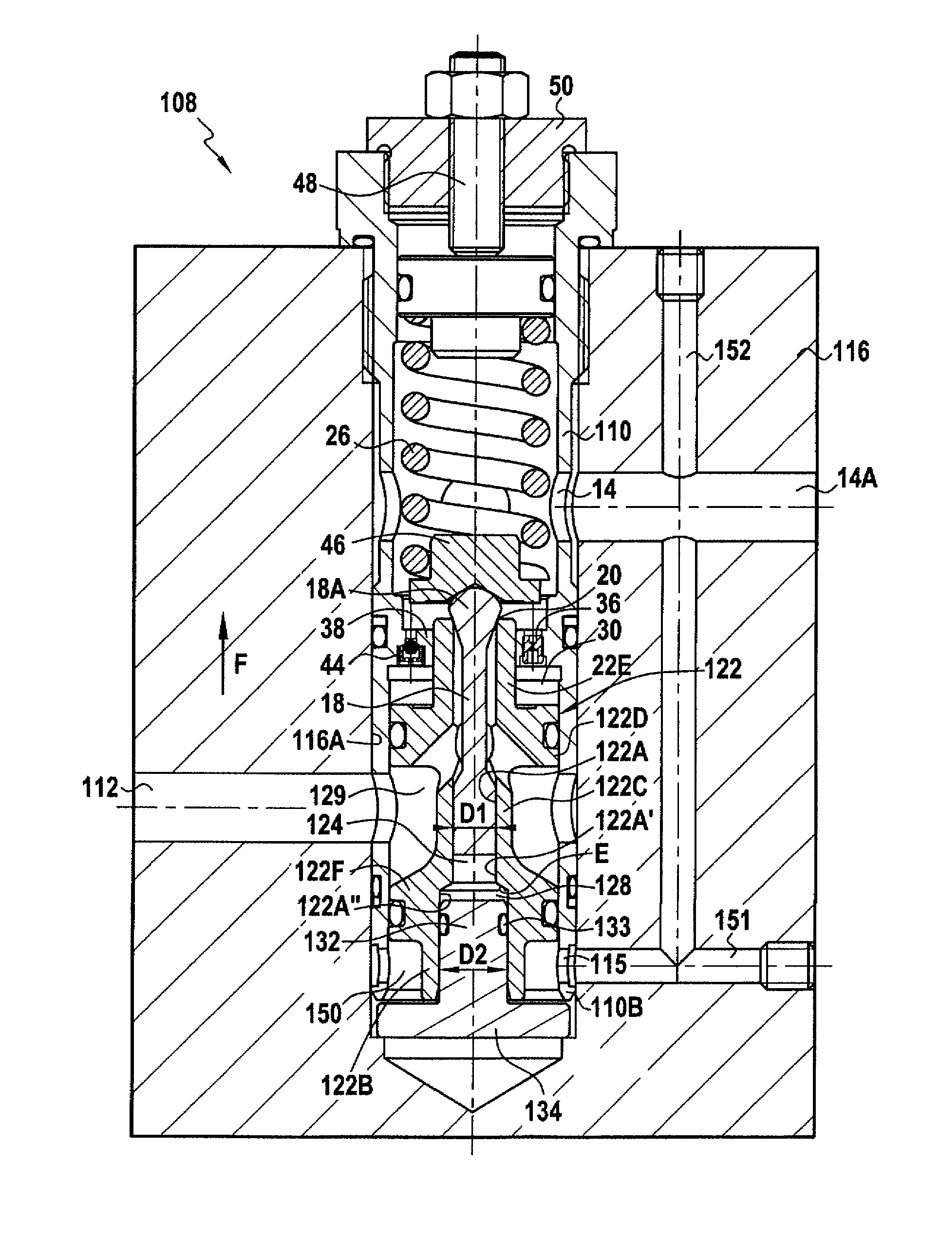
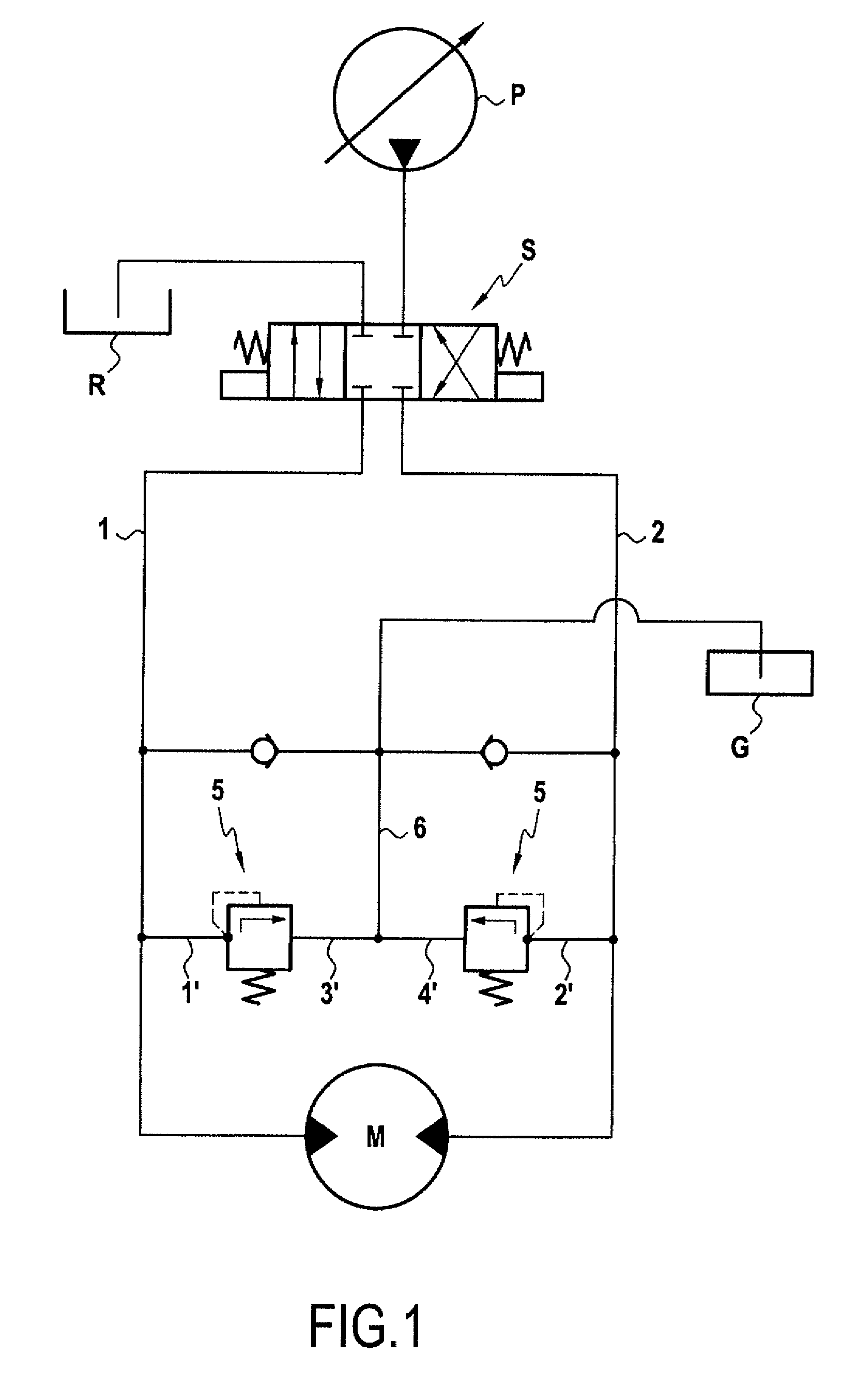
[0030]The circuit shown in FIG. 1 comprises a pump P for feeding fluid to a hydraulic motor M via two main ducts 1, 2 that serve respectively for feed and for discharge as a function of the position of a selector S. Although an open circuit is shown (the discharge duct being connected to a reservoir R at atmospheric pressure or at a very low pressure), it also possible to imagine the circuit being a closed circuit. Two conventional pressure limiters 5 serve to limit the pressure in the feed main duct. Their respective inlet valves 1′, and 2′ are connected to respective ones of the ducts 1 and 2, while their respective outlet ports 3′ and 4′ are connected to booster means G via a duct 6.

[0031]In a conventional variant, the pressure limiters 5 can have their respective inlet ports connected to respective ones of the ducts 1 and 2, while their respective outlet ports are connected to respective ones of the ducts 2 and 1.

[0032]These are conventional circuits in which two valves of the i...


PUM


Abstract

A valve including a valve body having an inlet port and an outlet port, a valve stem, a valve seat, an opening control chamber for the valve stem, which chamber, by being fed with fluid, urges the valve stem to move towards the open position of the valve, a return spring of opposing effect, and a piston suitable for sliding in the body so as to urge contact to be established between the valve stem and the seat. The valve seat is formed on the piston, which piston is provided with a bore in which the valve stem is in its closure movement, the fluid flows out via a constriction from a damping chamber.

Description

BACKGROUND OF THE INVENTION[0001]The present invention relates to a valve having damped opening, said valve comprising a valve body having an inlet port and an outlet port, a valve stem suitable for moving between a closed position in which said stem co-operates with a valve seat so as to isolate the inlet port and the outlet port from each other, and an open position in which the stem is spaced apart from the seat so as to put the inlet and the outlet ports into communication with each other, the valve further comprising an opening control chamber for the valve stem, which chamber is suitable for being fed with fluid so as to urge the valve stem to move towards its open position, a return spring for urging the valve stem to move towards its closed position, a piston suitable for sliding in the body in a closure movement for urging contact to be established between the valve stem and the seat, and hydraulic control means for causing the piston to move, which control means include a ...

Claims


Application Information

Patent Timeline
IPC IPC(8): F16K31/12
CPCF16K17/06G05D16/106F16K17/0433G05D16/109Y10T137/7835Y10T137/7781Y10T137/7834
Inventor COSTAZ, DOMINIQUEMANGANO, ALAIN
Owner POCLAIN HYDRAULICS IND
Why Eureka
Try Eureka