Wireless communication system and wireless terminal apparatus for sensor network

a wireless terminal and wireless communication technology, applied in the field of wireless communication systems, can solve the problems of difficult discrimination of each signal on the receiving sid

Inactive Publication Date: 2008-06-19
HITACHI LTD
View PDF7 Cites 76 Cited by
  • Summary
  • Abstract
  • Description
  • Claims
  • Application Information

AI Technical Summary

Benefits of technology

[0026]According to the present invention, since the conflict and congestion in communication not only between the wireless terminal apparatus and the base station but between wireless terminal apparatuses are effectively avoidable, the wireless terminal apparatus and a wireless communication system with few retransmitting operations of the same frame can be provided.

Problems solved by technology

In the system using such a wearable sensor node, when a plurality of nodes transmit infrared signals at the same timing, discrimination of each signal on the receiving side becomes difficult due to collision or overlapping of the transmission signals.

Method used


Image

  • Wireless communication system and wireless terminal apparatus for sensor network
  • Wireless communication system and wireless terminal apparatus for sensor network
  • Wireless communication system and wireless terminal apparatus for sensor network

Examples


first embodiment

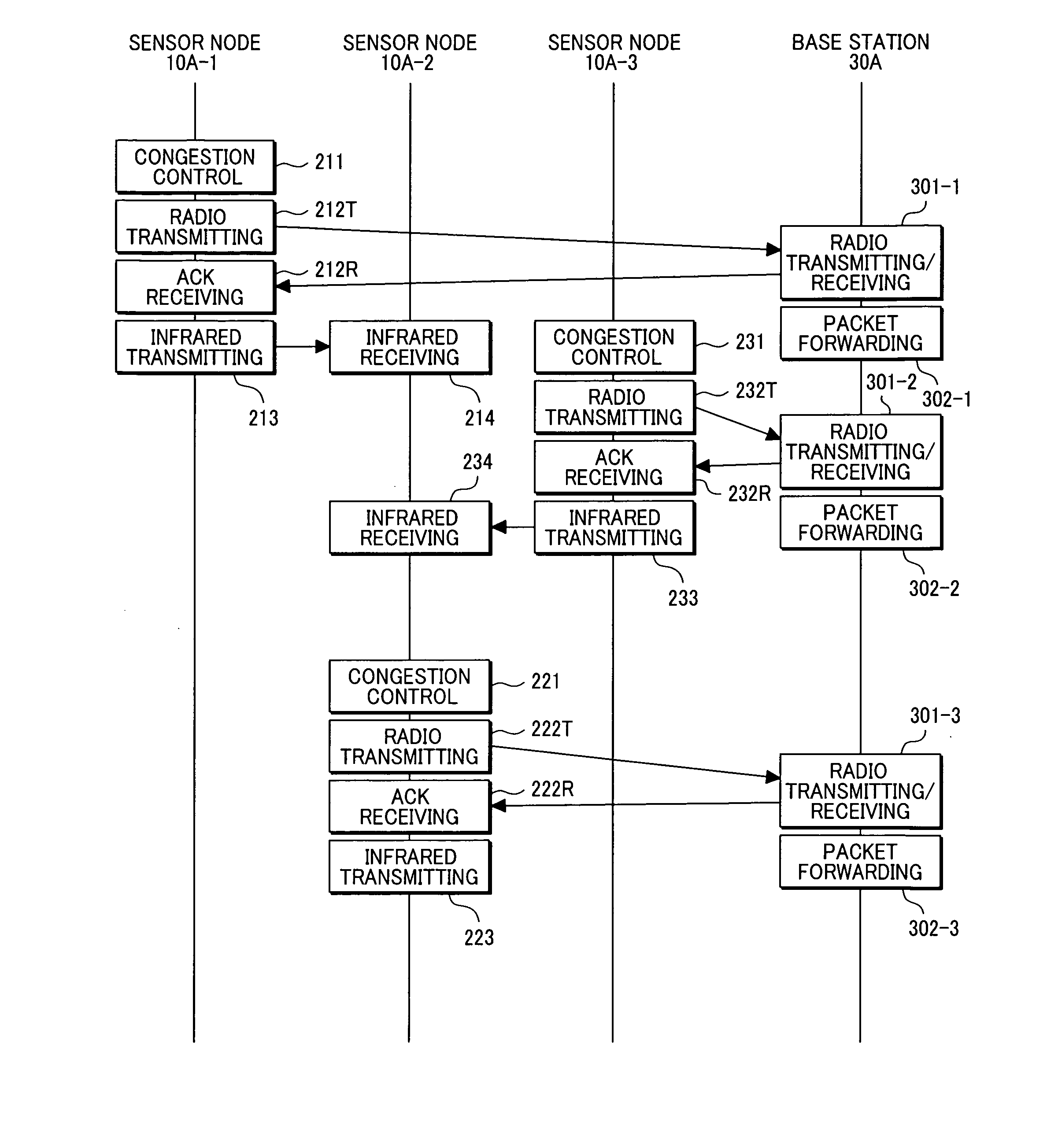
[0067]FIG. 4 shows a communication sequence between the sensor node 10 (10A-1 to 10A-3) and the base station 30A according to the present invention. It is assumed here that the sensor nodes 10A-1 and 10A-2 and the sensor nodes 10A-2 and 10A-3 are in the spatial relationship (in terms of distance and angle) in which an infrared communication is possible mutually, and that the sensor nodes 10A-1 and 10A-3 are in the spatial relationship in which an infrared communication is impossible.

[0068]The sensor node 10A-1 performs the congestion control (Step 211) by carrier sensing to confirm that the radio communication is in a collision-free state, and transmits a radio communication frame to the base station 30A (Step 212T). Upon succeeding in receiving the radio communication frame, the base station 30A returns an ACK frame to the sensor node 10A-1 (Step 301-1), and forwards to the server 40 the content of the received frame as a data packet (Step 302-1). Upon receiving the ACK signal from...

second embodiment

[0090]FIG. 9 shows a communication sequence between the sensor node10 (10A-1 to 10A-3) and the base station 30A according to the invention.

[0091]This embodiment is characterized by that each sensor node having completed the radio communication with the base station repeats transmission of the sensor node identifier by the infrared communication two or more times in the radio communication period T0.

[0092]As described before, each sensor node 10 performs the congestion control individually to start the radio communication (212, 222, 232 . . . ). For this reason, in the infrared communication performed immediately after the radio communication, each sensor node can transmit the node identifier without conflicting with other sensor nodes. However, in the second or later infrared communication performed in the same period T0, there is no guarantee that conflict with other sensor nodes can be avoided.

[0093]According to the present embodiment, as illustrated in FIG. 10, each sensor node p...


PUM


Abstract

A wireless terminal comprising a radio transceiver for communicating with a base station, an infrared transceiver for communicating with another wireless terminal, a congestion control unit for detecting whether radio communication with the base station is in a collision-free state, and a communication control unit for performing radio communication with the base station by the radio transceiver after detecting unoccupied state in the radio channel by the congestion control unit and transmitting identification information to another wireless terminal by the infrared transceiver when the radio communication with the base station is completed.

Description

CLAIM OF PRIORITY[0001]The present application claims priority from Japanese application serial No. 2006-337461, filed on Dec. 14, 2006, the content of which is hereby incorporated by reference into this application.BACKGROUND OF THE INVENTION[0002](1) Field of the Invention[0003]The present invention relates to a wireless communication system, more specifically to a wireless communication system and a wireless terminal apparatus suitable for a sensor network which collects information from a plurality of wireless terminals each provided with a sensor.[0004](2) Description of Related Art[0005]Research and development of a network system which collects information in real time from a small wireless terminal apparatus carrying a sensor are progressing these days. Hereinafter, such a network system is called a sensor network and the small wireless terminal apparatus carrying a sensor is called a sensor node. The sensor network is a network system in which the status of a person, an obj...

Claims


Application Information

Patent Timeline
Patent Type & Authority Applications(United States)
IPC IPC(8): G08B23/00H04B1/3822H04B1/40H04W28/00H04W74/08H04W84/12H04W84/18
CPCH04W84/18H04W74/0808
Inventor WAKISAKA, YOSHIHIROOHKUBO, NORIOMORIWAKI, NORIHIKOHAYAKAWA, MIKI
Owner HITACHI LTD
Why Eureka
Try Eureka