Liquid droplet ejecting head and liquid droplet ejecting apparatus

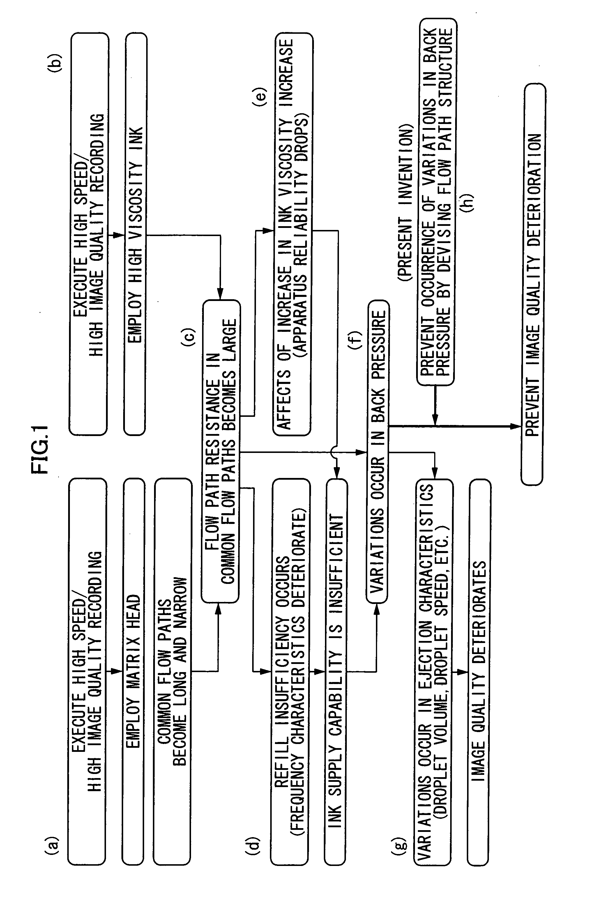
a liquid droplet and ejecting head technology, which is applied in the direction of printing, inking apparatus, etc., can solve the problems of large path resistance, difficult to execute stable liquid droplet ejection, and overly large flow path resistance in common flow paths

Inactive Publication Date: 2008-06-19
FUJIFILM BUSINESS INNOVATION CORP
View PDF13 Cites 43 Cited by
  • Summary
  • Abstract
  • Description
  • Claims
  • Application Information

AI Technical Summary

Problems solved by technology

However, when a high viscosity ink and a matrix type head are combined, there has been the problem that the flow path resistance in the common flow paths becomes overly large and executing stable liquid droplet ejection becomes difficult.
That is, in a matrix type head, it is difficult to ensure a large cross-sectional area in the common flow paths and it is easy for the flow path resistance to become large because the common flow paths are disposed between each of the ejectors.
The head size increases when the cross-sectional area of the common flow paths is increased, which becomes a problem in terms of high densification of dots and apparatus size.
In addition, when a high viscosity ink is used in a common flow path whose cross-sectional area is small, the flow path resistance in the common flow path becomes extremely large; thus, sufficient ink supply can no longer be performed with respect to each of the ejectors, and it becomes difficult to execute stable liquid droplet ejection at a high frequency.
However, in this conventional matrix type head to which ink circulation is applied, there has been the problem that variations in back pressure resulting from the flow path resistance in the common flow paths occur.
As a result, realizing high image quality recording becomes impossible.
Moreover, as another problem when a high viscosity ink is used, there is the problem that ink viscosity increases in the vicinities of the nozzles.
When such an ink viscosity increase occurs, this causes problems such as the ejector becoming unable to perform proper ink ejection, the droplet volume and the droplet speed becoming reduced, and non-ejection occurring.

Method used


Image

  • Liquid droplet ejecting head and liquid droplet ejecting apparatus
  • Liquid droplet ejecting head and liquid droplet ejecting apparatus
  • Liquid droplet ejecting head and liquid droplet ejecting apparatus

Examples


first embodiment

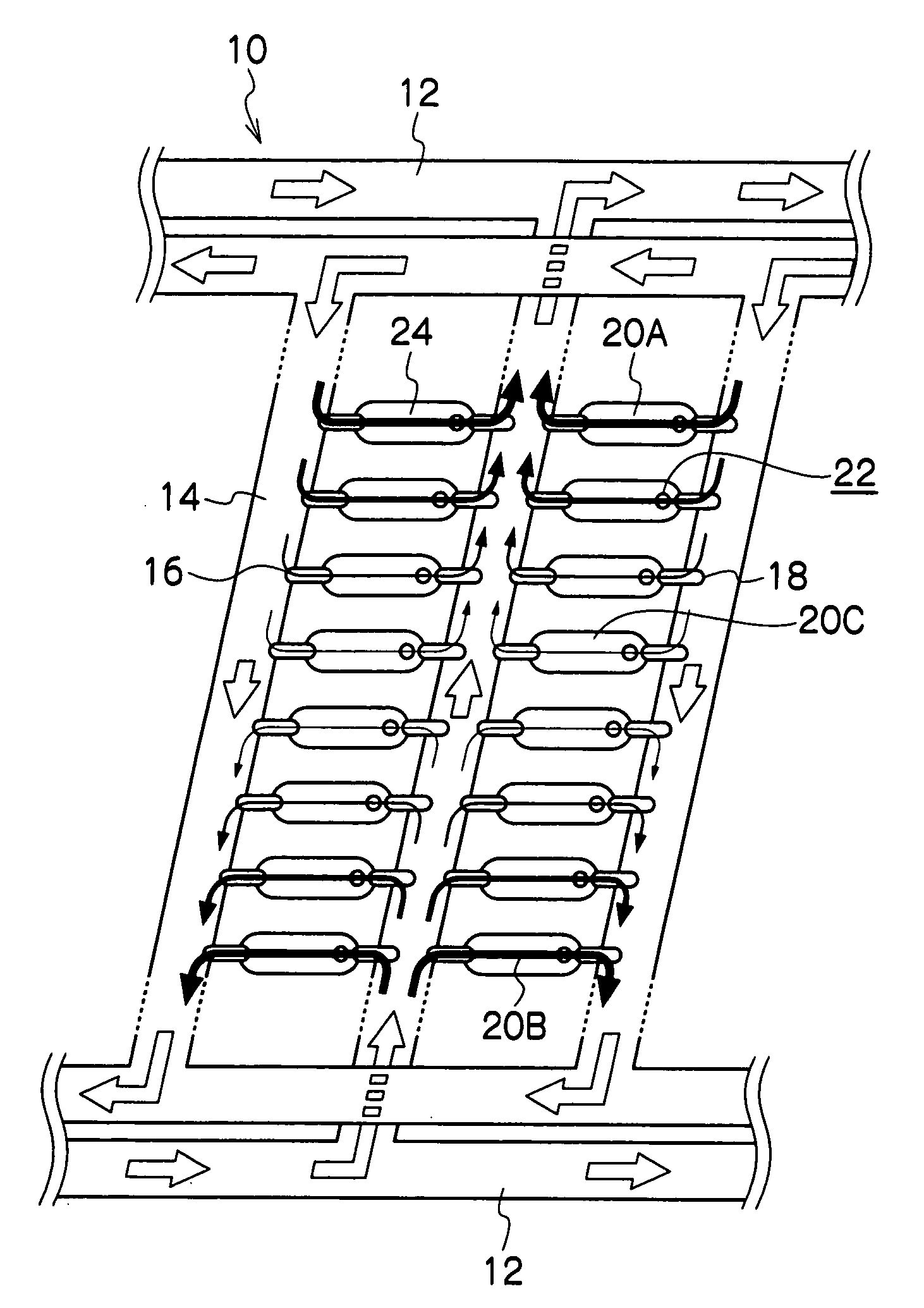
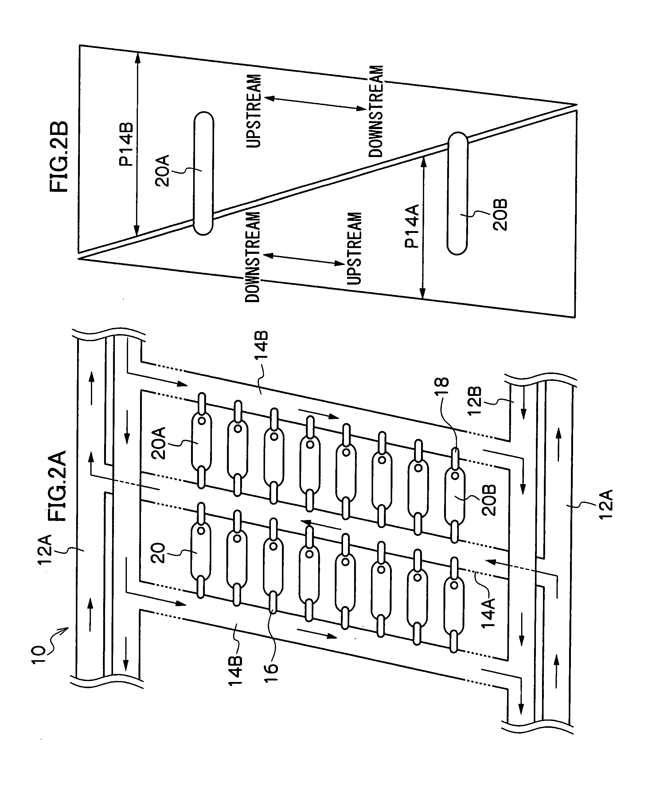
[0031]In FIGS. 2A and 2B, there is shown a liquid droplet ejecting head 10 relating to a first exemplary embodiment of the present invention.

[0032]As shown in FIGS. 2A and 2B, ejectors 20 are two-dimensionally arrayed in a matrix in the liquid droplet ejecting head 10, common flow paths 14A and 14B whose liquid flow directions are different are alternately disposed between columns of the ejectors 20, and ink is supplied to the common flow paths 14A and 14B from common flow path mainstreams 12A and 12B.

[0033]The common flow path mainstreams 12A and 12B supply ink to the common flow paths 14A and 14B, which supply ink to each of the ejectors 20 via first communicating paths 16 and second communicating paths 18. Thus, back pressure resulting from the liquid flows in opposite directions acts on the ejectors 20 from the first communicating paths 16 and the second communicating paths 18.

[0034]That is, the present embodiment is characterized in that the directions of the ink circulation fl...


PUM


Abstract

A liquid droplet ejecting head that drives pressure generating portions disposed in pressure chambers inside ejectors to thereby pressurize liquid inside the pressure chambers and cause liquid droplets to be ejected from nozzles communicated with the pressure chambers, wherein the ejectors are connected at a plurality of places via a plurality of communicating paths to common flow paths in which forcible liquid flows are formed, is provided.

Description

CROSS REFERENCE TO RELATED APPLICATION[0001]This application is based on and claims priority under 35 USC 119 from Japanese Patent Application No. 2006-340217 filed on Dec. 18, 2006.BACKGROUND[0002]1. Technical Field[0003]The present invention relates to a liquid droplet ejecting head and a liquid droplet ejecting apparatus, and in particular to an inkjet recording head and an inkjet recording apparatus that eject extremely small ink droplets with piezoelectric elements.[0004]2. Related Art[0005]In recent years, in liquid droplet ejecting apparatus represented by inkjet printers, there has been a demand to achieve a balance between high image quality recording and high speed recording. In particular, there has been a strong demand for liquid droplet ejecting apparatus that can execute recording with high image quality even with respect to plain paper in which ink bleeding and show-through easily occur.[0006]For performing high image quality recording with respect to plain paper, usi...

Claims


Application Information

Patent Timeline
Patent Type & Authority Applications(United States)
IPC IPC(8): B41J2/045
CPCB41J2/14233B41J2202/12B41J2202/11
Inventor OKUDA, MASAKAZU
Owner FUJIFILM BUSINESS INNOVATION CORP
Why Eureka
Try Eureka