Apparatus and method for driving self-emission display panel

a display panel and display panel technology, applied in the field of self-emission display panel driving, can solve the problems of increasing the cost of switching elements, increasing the number of cells simultaneously, and increasing the voltage and rippling of driving waves. the effect of reducing the number of cells

Inactive Publication Date: 2008-06-19
SAMSUNG ELECTRONICS CO LTD
View PDF5 Cites 11 Cited by
  • Summary
  • Abstract
  • Description
  • Claims
  • Application Information

AI Technical Summary

Benefits of technology

[0016]An aspect of the present invention is to provide an apparatus and a method for driving a self-emission display panel by which a maximum value of a peak current generated in a sustain section of a SF can be reduced to solve discharge, luminance deviation, and luminance difference problems, and a cost problem of a switching element.
[0017]In one aspect of the present invention, there is provided an apparatus for driving a self-emission display panel, including: a sustain pulse (STP) controller calculating an automatic power control (APC) level of image data having an input grayscale and outputting a STP corresponding to the calculated APC level; a sub-field (SF) controller generating SF data for applying a dithering method to each SF corresponding to the input grayscale to express the grayscale so as to reduce the number of cells simultaneously emitting light in a SF; a sustain / scan driver generating sustain / scan pulses from the output STP to drive the self-emission display panel; and an address electrode driver generating an address driving signal corresponding to the input grayscale from the generated SF data to drive the self-emission display panel.

Problems solved by technology

However, the average current of a peak current for one frame is much smaller than “852×480'3.” Thus, if a peak current is generated by “852×480×3” voltage falling and rippling of driving waves become serious.
Thus, voltage falling occurs along electrode lines X and Y. As a result, luminance becomes non-uniform at parts adjacent to centers of the electrode lines X and Y and electrode pads.
Thus, cost of the switching element may be increased.

Method used


Image

  • Apparatus and method for driving self-emission display panel
  • Apparatus and method for driving self-emission display panel
  • Apparatus and method for driving self-emission display panel

Examples


Embodiment Construction

[0055]Hereinafter, exemplary embodiments of the present invention will be described in detail with reference to the accompanying figures.

[0056]In the following description, same drawing reference numerals are used for the same elements even in different drawings. The matters defined in the description such as a detailed construction and elements are nothing but the ones provided to assist in a comprehensive understanding of the invention. Thus, it is apparent that the present invention can be carried out without those defined matters. Also, well-known functions or constructions are not described in detail since they would obscure the invention in unnecessary detail.

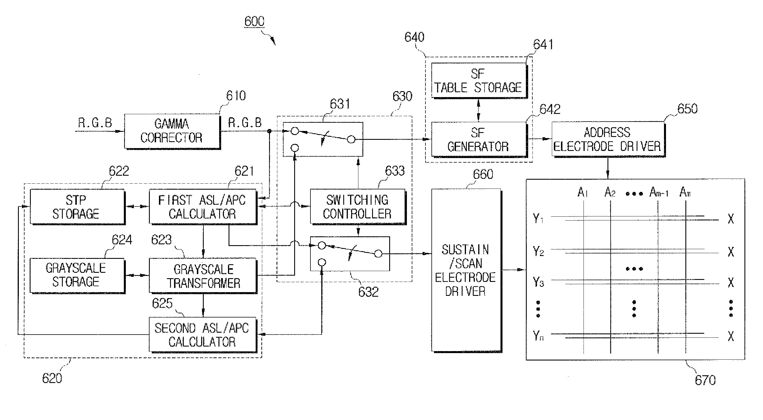
[0057]FIG. 5 is a schematic block diagram of an apparatus for driving a self-emission display panel according to an exemplary embodiment of the present invention. Only blocks related to the exemplary embodiment of the present invention are illustrated in FIG. 5, and illustrations and descriptions of blocks obscuring the e...


PUM


Abstract

Provided are an apparatus and a method for driving a self-emission display panel. A sustain pulse (STP) controller calculates an automatic power control (APC) level of image data having an input grayscale and outputs a STP corresponding to the calculated APC level. A sub-field (SF) controller which applies a dithering method to each SF corresponding to the input grayscale to generate SF data for expressing the input grayscale so as to reduce the number of cells simultaneously emitting light in a SF. A sustain/scan driver generates sustain/scan pulses from the output STP to drive the self-emission display panel. An address electrode driver generates an address driving signal corresponding to the input grayscale from the generated SF data to drive the self-emission display panel.

Description

CROSS-REFERENCE TO RELATED APPLICATIONS[0001]This application priority from Korean Patent Application No. 2006-101393, filed Oct. 18, 2006, in the Korean Intellectual Property Office, the entire contents of which is incorporated herein by reference.BACKGROUND OF THE INVENTION[0002]1. Field of the Invention[0003]Apparatuses and methods consistent with the present invention relate to driving a self-emission display panel, and more particularly, to driving a self-emission display panel by which the number of sustain pulses (STPs) necessary for emitting image data can be reduced according to a grayscale of the image data and a consumed power can be maintained constant.[0004]2. Description of the Related Art[0005]Plasma display panels (PDPs) use an address display separating (ADS) driving method, i.e., a method of dividing a frame into a plurality of sub-fields (SFs) and then driving the SFs, in order to realize grayscales of images. FIG. 1 is a view illustrating an example of a frame wh...

Claims


Application Information

Patent Timeline
Patent Type & Authority Applications(United States)
IPC IPC(8): G06K15/00G09G3/288G09G3/294
CPCG09G3/2022G09G3/2051G09G3/2944G09G2360/16G09G2320/0271G09G2330/021G09G2330/025G09G2320/0233G09G3/296
Inventor MOON, GWON-JIN
Owner SAMSUNG ELECTRONICS CO LTD
Why Eureka
Try Eureka