
Magnetic disk drive and suspension assembly adopted therein

a technology of magnetic disk drive and suspension assembly, which is applied in the direction of maintaining head carrier alignment, recording information storage, instruments, etc., can solve the problems of assembly plastic deformation, increase cost, and error

Active Publication Date: 2008-06-19
WESTERN DIGITAL TECH INC
View PDF22 Cites 23 Cited by
  • Summary
  • Abstract
  • Description
  • Claims
  • Application Information

AI Technical Summary

Benefits of technology

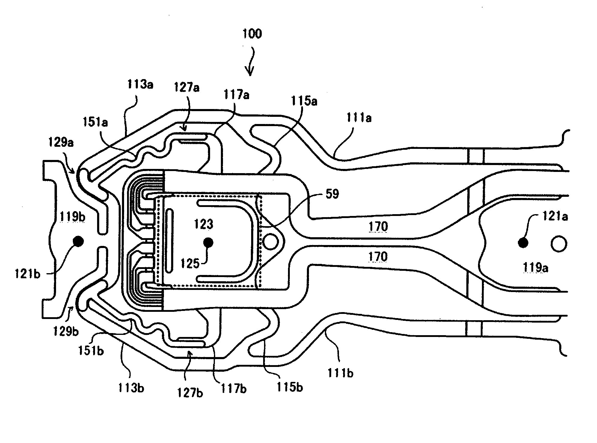
[0016]It is an object of embodiments of the present invention to provide a suspension assembly having a dielectric limiter that does not affect a pivotal motion and is suitable for miniaturization. Another object of embodiments of the invention is to provide a suspension assembly having a dielectric limiter that can be formed without mechanical work. Still another object of embodiments of the invention is to provide a suspension assembly having a dielectric limiter that can be formed in a manufacturing process of an insulating layer of the suspension assembly. A further object of embodiments of the invention is to provide a magnetic disk drive adopting such a suspension assembly.

Problems solved by technology

An error can occur when the head / slider is positioned over the track due to various manufacturing errors occurring in different components making up the magnetic disk drive or irregularity in behavior of an air bearing or the suspension assembly.
When the displacement exceeds a certain level, the flexure assembly is plastic-deformed and cannot perform a given pivotal motion.
Disadvantageously, the limiter of such a structure requires the bending work of the flexure, which increases costs, and a space for the limiter is needed, which is not appropriate for miniaturization.

Method used


Image

  • Magnetic disk drive and suspension assembly adopted therein
  • Magnetic disk drive and suspension assembly adopted therein
  • Magnetic disk drive and suspension assembly adopted therein

Examples


Embodiment Construction

[0015]Embodiments of the present invention relate to a limiter structure of a suspension assembly adopted in a magnetic disk drive, and more particularly, to a limiter structure suitable for making a suspension assembly smaller.

[0016]It is an object of embodiments of the present invention to provide a suspension assembly having a dielectric limiter that does not affect a pivotal motion and is suitable for miniaturization. Another object of embodiments of the invention is to provide a suspension assembly having a dielectric limiter that can be formed without mechanical work. Still another object of embodiments of the invention is to provide a suspension assembly having a dielectric limiter that can be formed in a manufacturing process of an insulating layer of the suspension assembly. A further object of embodiments of the invention is to provide a magnetic disk drive adopting such a suspension assembly.

[0017]According to an aspect of one embodiment of the invention, a suspension ass...


PUM

PropertyMeasurementUnit
thicknessaaaaaaaaaa
thicknessaaaaaaaaaa
widthaaaaaaaaaa

Abstract

Embodiments of the present invention provide a suspension assembly having a dielectric limiter. According to one embodiment, the suspension assembly includes a load beam and a flexure assembly. The flexure assembly includes a metal layer where there are formed a fixing portion fixed to the load beam, main rings, and extending from the fixing portion, sub-rings, and a flexure tongue having moving-side limiter coupling portions defined thereon. Fixing-side limiter coupling portions are defined at the main rings. Dielectric limiters each have a gross length larger than a between-coupling-portions distance between a fixing-side limiter coupling portion and a moving-side limiter coupling portion, and couple the fixing-side limiter coupling portion to the moving-side limiter coupling portion.

Description

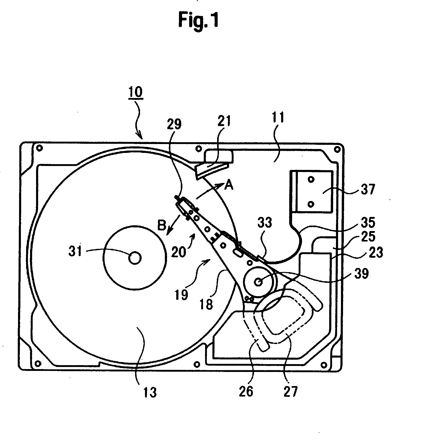
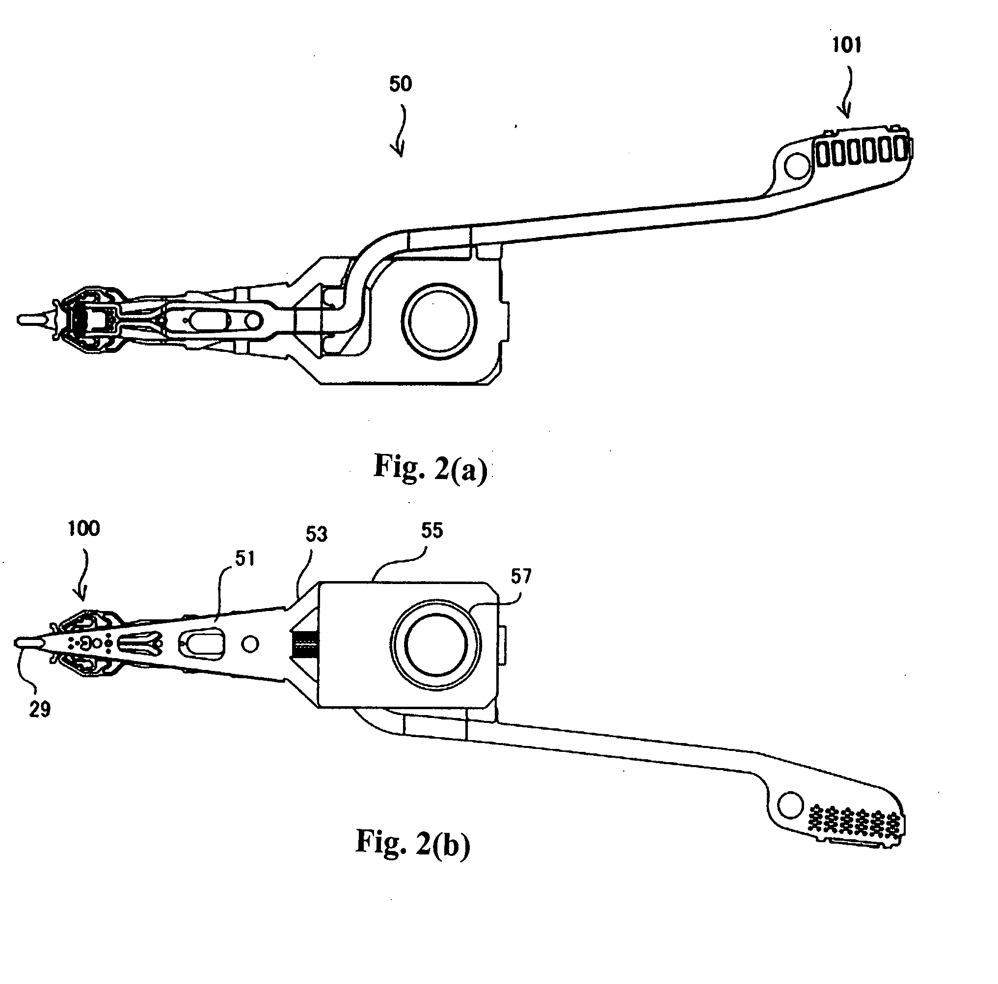
CROSS-REFERENCES TO RELATED APPLICATIONS[0001]The instant nonprovisional patent application claims priority to Japanese Patent Application No. 2006-336467 filed Dec. 14, 2006 and which is incorporated by reference in its entirety herein for all purposes.BACKGROUND OF THE INVENTION[0002]In a magnetic disk drive, a head / slider flies at a very slight height (flying height) over a rotating magnetic disk. The head / slider is mounted to a suspension assembly and supported over the magnetic disk. The suspension assembly includes a load beam and a flexure assembly, and the flexure assembly includes a flexure tongue. The head / slider is mounted to the flexure tongue.[0003]The suspension assembly is mounted to an actuator unit and moves rotationally over the magnetic disk. A structure in which the head / slider is mounted to the suspension assembly is called a head gimbal assembly (HGA). A magnetic head formed on the head / slider needs to be accurately positioned over a track during read / write ope...

Claims


Application Information

Patent Timeline
Patent Type & Authority Applications(United States)
IPC IPC(8): G11B5/48G11B5/60
CPCG11B5/4853
Inventor MURAKI, TAKUMATSUCHIDA, HIROYASUHIRAMATSU, TOMOKISUMIYA, TAKEJI
Owner WESTERN DIGITAL TECH INC
Learn More