Vehicle lamp

a technology for vehicles and lamps, applied in fixed installations, lighting and heating apparatus, lighting support devices, etc., can solve the problems of insufficient amount of light irradiation, difficult to configure lamps to be sufficiently slim, and inability to ensure the length of lamps in front-and-back directions. to achieve the effect of precise control of light distribution

Inactive Publication Date: 2008-06-19
KOITO MFG CO LTD
View PDF5 Cites 50 Cited by
  • Summary
  • Abstract
  • Description
  • Claims
  • Application Information

AI Technical Summary

Benefits of technology

[0006]It is an object of the present invention to attain a vehicle lamp having a slim profile and to ensure a sufficient amount of light irradiation in a vehicle lamp having a light emitting element as a light source while maintaining precise control of a light distribution.

Problems solved by technology

However, because the light emitting element is positioned in the vicinity of the rear focal point of the convex lens, the lamp cannot be configured to have a shorter length in the front-and-rear direction.
Thus, it is difficult to configure the lamp to be sufficiently slim.
Therefore, a sufficient amount of light irradiation cannot be ensured.

Method used


Image

  • Vehicle lamp
  • Vehicle lamp
  • Vehicle lamp

Examples


first exemplary embodiment

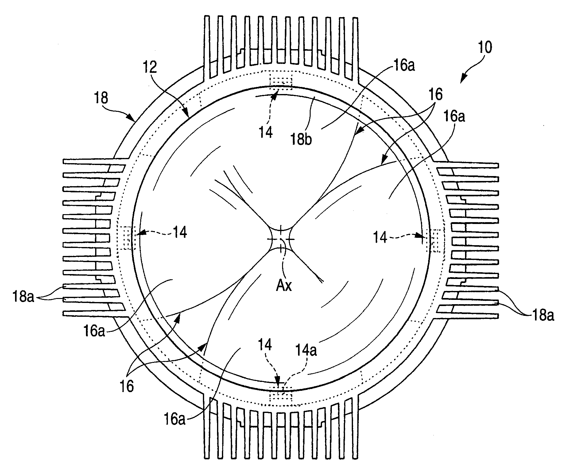
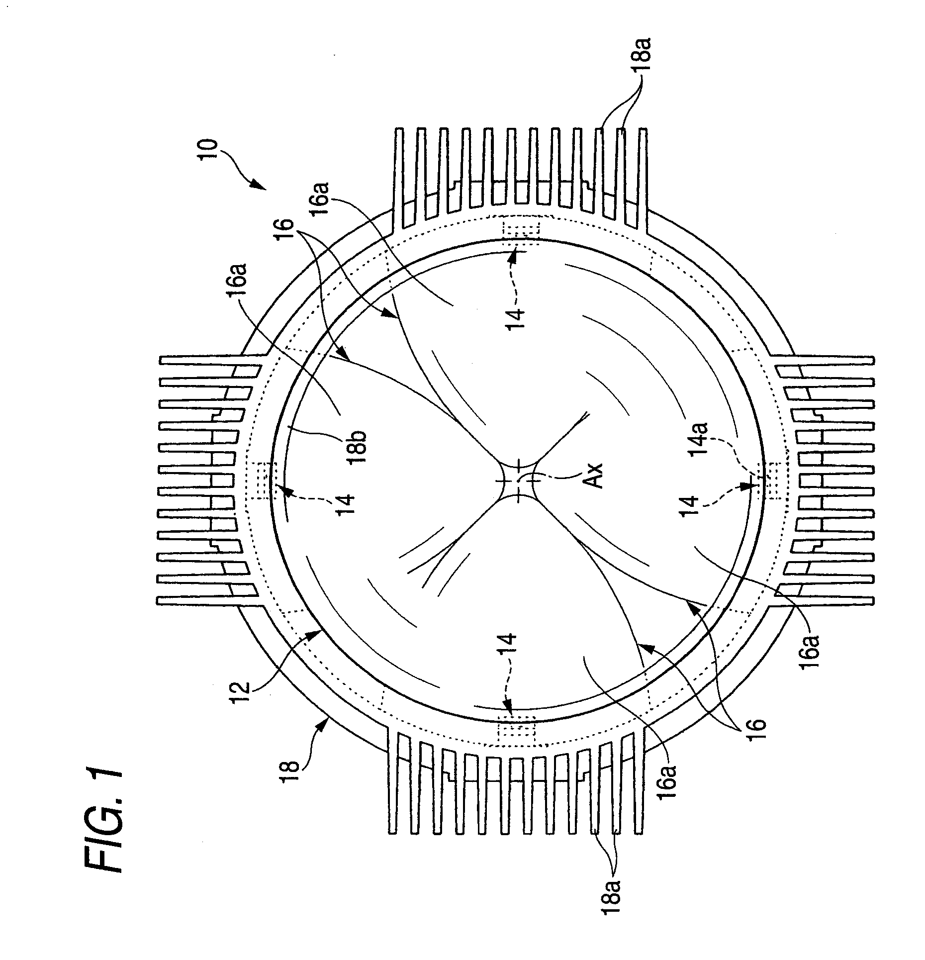
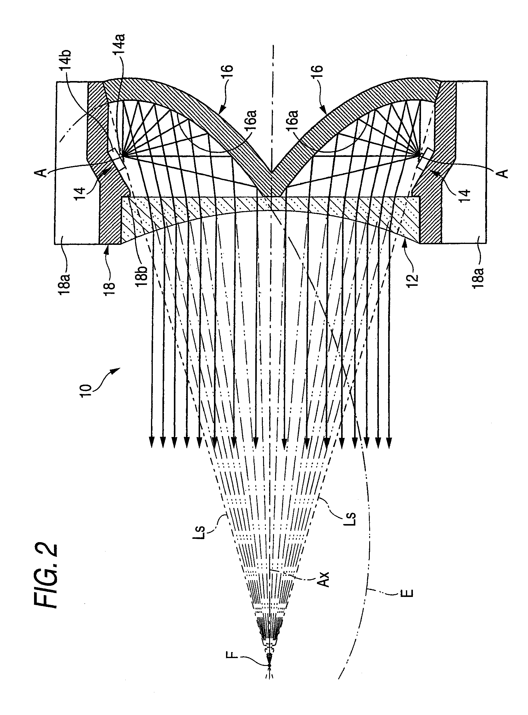
[0037]As shown in the FIGS. 1 and 2, a vehicle lamp 10 according to a first exemplary embodiment of the present invention includes a concave lens 12 disposed on an optical axis Ax extending in a front-and-rear direction of the lamp 10 (i.e., in a direction behind and in front of the page), four light emitting elements 14 disposed behind the concave lens 12, fourth reflectors 16, and a lens holder 18. The vehicle lamp 10 is used as a lamp unit of a vehicle headlamp in a state in which it is incorporated to enable a regulation of the optical axis for a lamp body (not shown). In that case, the vehicle lamp 10 serves to irradiate a light for forming a part of a high beam light distribution pattern in a state in which the optical axis Ax is disposed to be extended in a front-and-rear direction of the vehicle.

[0038]The concave lens 12 in this exemplary embodiment is a planoconvex aspherical lens in which a front side surface is a concave surface and a rear side surface is a plane, and is ...

second exemplary embodiment

[0061]FIG. 4 is a side sectional view showing a vehicle lamp 110 according to a second exemplary embodiment.

[0062]As shown in FIG. 4, the vehicle lamp 110 according to the second exemplary embodiment has a basic structure which is similar to that of the vehicle lamp 10 according to the first exemplary embodiment and is different from that in the first exemplary embodiment in that a concave lens 112 is a Fresnel lens.

[0063]Also in the case in which the structure according to the second exemplary embodiment is employed, it is possible to obtain the similar advantages as those in the first exemplary embodiment. By employing the structure according to the second exemplary embodiment, moreover, it is possible to reduce a thickness of the concave lens 112 itself, thereby promoting a reduction in the thickness of the lamp still more.

third exemplary embodiment

[0064]FIG. 5 is a front view showing a vehicle lamp 210 according to a third exemplary embodiment.

[0065]As shown in FIG. 5, the vehicle lamp 210 according to the third exemplary embodiment has a basic structure as that of the vehicle lamp 10 according to the first exemplary embodiment. However, in the vehicle lamp 210, two of the four reflectors, i.e., the upper and lower reflectors 216 shown in FIG. 5, have different structures from those in the first exemplary embodiment.

[0066]In other words, structures of the left and right reflectors 16 are the same as those in the first exemplary embodiment. However, for the upper and lower reflectors 216, a shape of a reflecting surface 216a is different from that of the first exemplary embodiment.

[0067]More specifically, the reflecting surface 216a of each of the reflectors 216 has a sectional shape taken along a vertical plane which is formed by the ellipse E as in the first exemplary embodiment, but the sectional shape is a curved surface o...


PUM


Abstract

A vehicle lamp is provided. The vehicle lamp includes a lens disposed on an optical axis of the vehicle lamp, the optical axis extending in a front-and-rear direction of the vehicle lamp, the lens comprising a first concave lens portion; a plurality of light emitting elements disposed to a rear side of the lens and around the optical axis at regular intervals in a circumferential direction, the plurality of light emitting elements comprising at least one first light emitting element disposed to a rear side of the first concave lens portion; at least one first reflector corresponding to the at least one first light emitting element and disposed between the corresponding first light emitting element and the optical axis, wherein the first reflector comprises a first reflecting surface which reflects light from the corresponding first light emitting element toward the first concave lens portion.

Description

FIELD OF THE PRESENT INVENTION[0001]Apparatuses consistent with the present invention relate to vehicle lamps, and more particularly, to vehicle lamps which use a light emitting element as a light source.DESCRIPTION OF THE RELATED ART[0002]In recent years, a light emitting element such as a light emitting diode has been developed as a light source of a vehicle lamp.[0003]For example, there is a vehicle lamp having a convex lens disposed on an optical axis extending in a front-and-rear direction of the lamp and a light emitting element disposed in the vicinity of a rear focal point of the convex lens (see, e.g., JP 2005-044683 A). The convex lens deflects a direct light emitted from the light emitting element and irradiates the light in a forward direction of the lamp.[0004]This arrangement allows precise control of the direct light from the light emitting element.[0005]However, because the light emitting element is positioned in the vicinity of the rear focal point of the convex len...

Claims


Application Information

Patent Timeline
Patent Type & Authority Applications(United States)
IPC IPC(8): F21V7/00
CPCF21S48/1159F21V29/763F21S48/1388F21S48/1747F21S48/328F21V5/045F21V7/0008F21V7/07F21V7/08F21V13/04F21V29/004F21Y2101/02F21V29/505F21V29/75F21S48/1163F21Y2115/10F21S41/143F21S41/147F21S41/255F21S41/275F21S41/321F21S41/365F21S41/663F21S45/48F21S41/155
Inventor YAGI, TAKAYUKIKOMATSU, MOTOHIRO
Owner KOITO MFG CO LTD
Why Eureka
Try Eureka