RF transmitter with predistortion and method therefor

a technology of rf transmitter and predistortion, applied in the field of radiofrequency (rf) communication, can solve the problems of spectral regrowth, signal distortion resulting from nonlinear amplification, and the inability to provide linear amplification, etc., and achieve the effect of reducing the cost of rf transmitters

Inactive Publication Date: 2008-06-19
CRESTCOM INC
View PDF85 Cites 70 Cited by
  • Summary
  • Abstract
  • Description
  • Claims
  • Application Information

AI Technical Summary

Benefits of technology

[0011]It is an advantage of at least one embodiment of the present invention that an improved RF transmitter with predistortion and a method therefor are provided.
[0012]Another advantage of at least one embodiment of the present invention is that a feedback loop is prevented from becoming inaccurate and possibly unstable at least in part because intermodulation products are attenuated in a feedback signal used by an RF transmitter to adjust tap coefficients in an adaptive equalizer that serves as a linear predistorter.
[0013]Another advantage of at least one embodiment of the present invention is that signal cancellation is used to remove intermodulation products from a feedback signal.
[0014]Another advantage of at least one embodiment of the present invention is that a baseline communication signal is used to form an intermodulation-estimate signal that, when combined with a feedback signal, cancels an intermodulation product.

Problems solved by technology

RF transmitters that attempt to provide linear amplification may suffer from a variety of signal distortions.
In such applications, real-world RF amplifiers fail to provide perfectly linear amplification, causing spectral regrowth to occur.
Since modern regulations place strict limitations on the amount of spectral regrowth that may be tolerated, any signal distortion resulting from nonlinear amplification poses a serious problem for RF transmitter designs.
In addition, any linear distortion in the transmitted RF communication signal is undesirable because linear distortion must be overcome in a receiver, often by necessitating transmission at greater power levels than would otherwise be required.
Linear distortions also complicate the spectral regrowth problem.
But as such techniques get more exotic, the analog component costs increase, and often increase dramatically.

Method used


Image

  • RF transmitter with predistortion and method therefor
  • RF transmitter with predistortion and method therefor
  • RF transmitter with predistortion and method therefor

Examples


Embodiment Construction

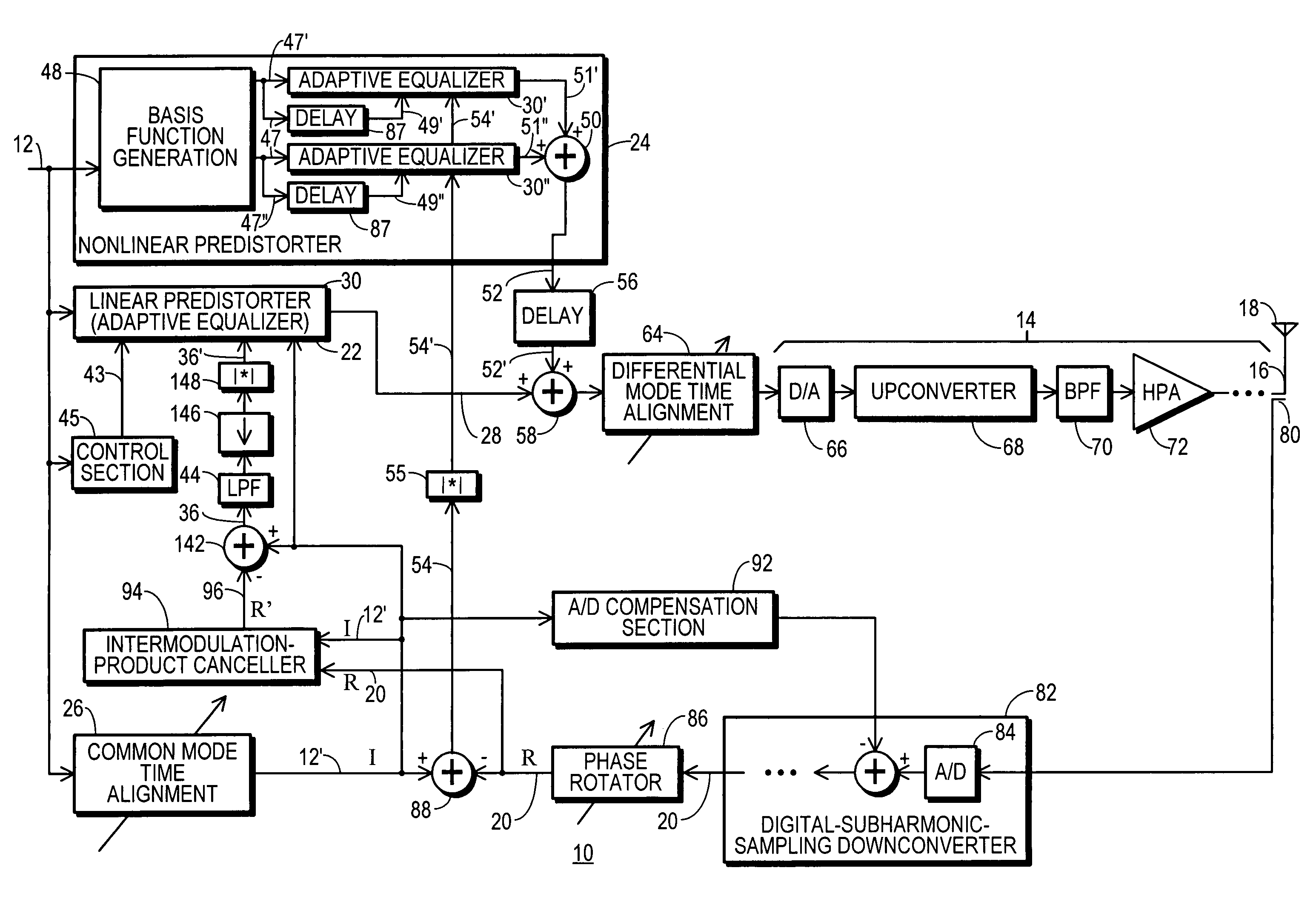
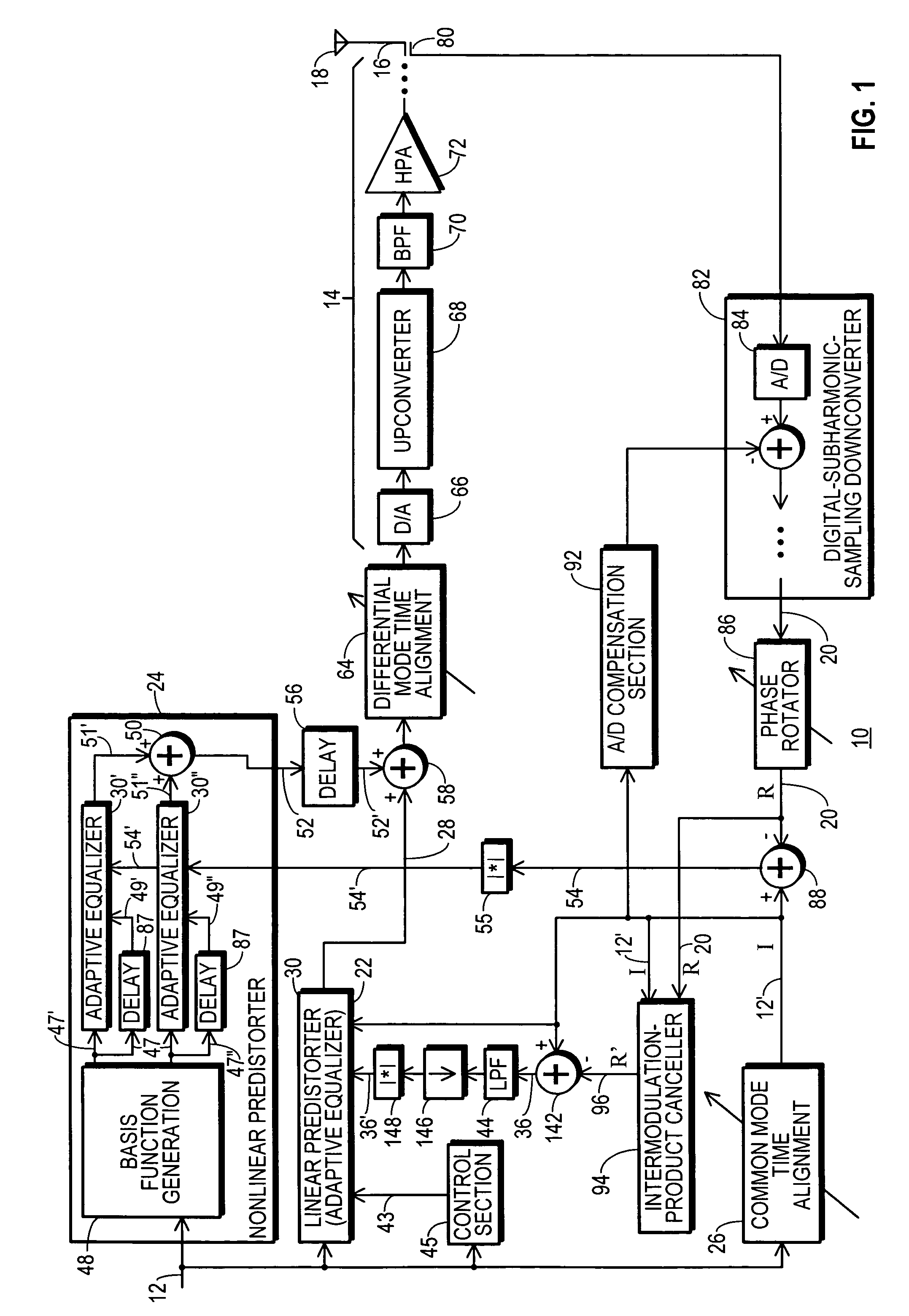
[0029]FIG. 1 shows a block diagram of an RF transmitter 10 configured in accordance with one embodiment of the present invention. RF transmitter 10 is adapted to receive a baseline communication signal 12.

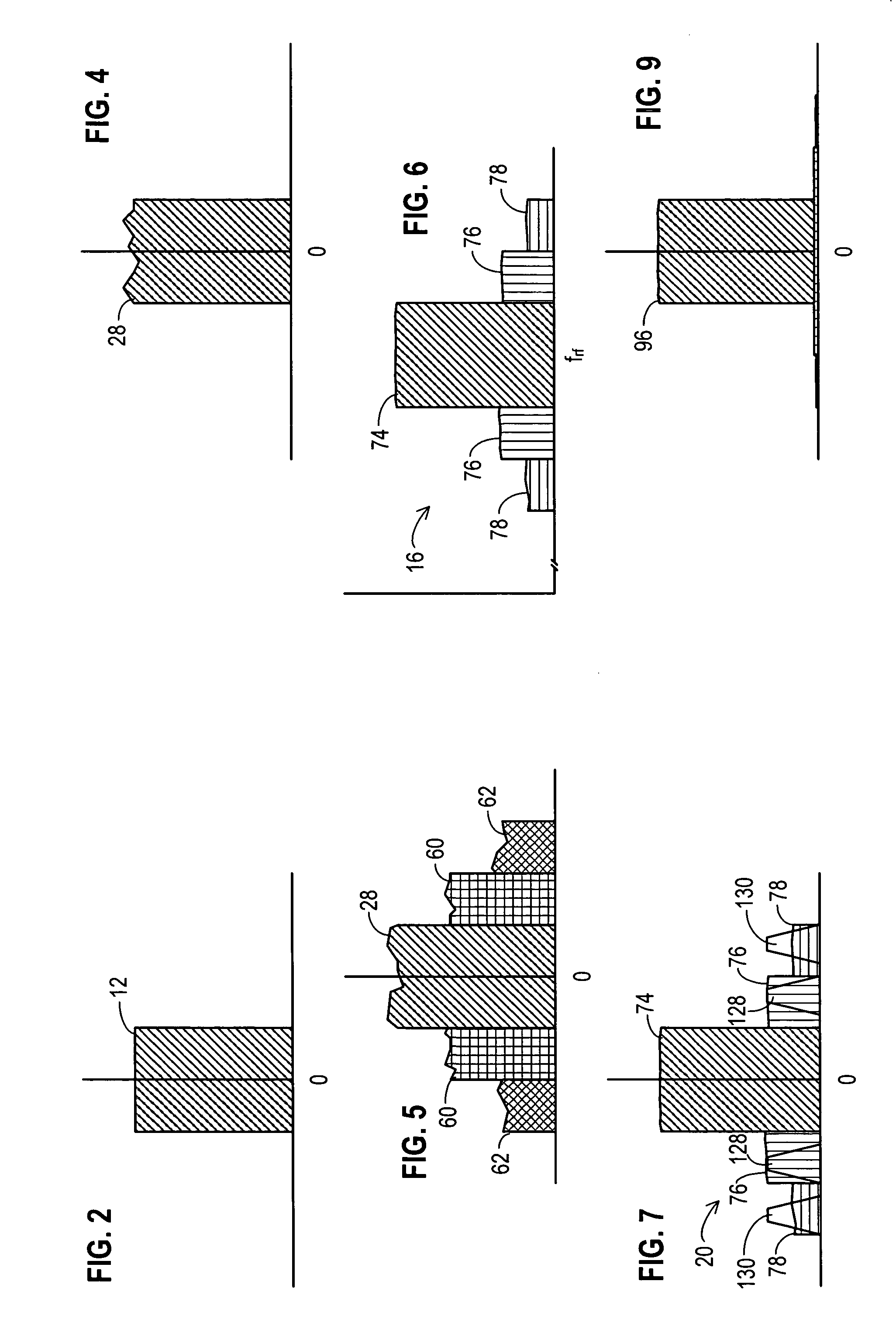
[0030]FIG. 2 graphically shows a spectral representation of baseline communication signal 12. Referring to FIGS. 1 and 2, in the preferred embodiment, baseline communication signal 12 is a complex digital signal having in-phase and quadrature components, preferably frequency-located at baseband. Hence, FIG. 2 depicts baseline communication signal 12 located at a frequency of zero, but this is not a requirement of the present invention.

[0031]As received at transmitter 10, baseline communication signal 12 has been digitally modulated to convey any and all data to be communicated by RF transmitter 10, using any of a wide variety of digital modulation techniques known to those skilled in the art. In addition, pulse-shape filtering may have been applied to reduce intersymbol interferenc...


PUM


Abstract

An RF transmitter (10) includes a linear predistorter (22) and a nonlinear predistorter (24) which together drive analog transmitter components (14). The linear and nonlinear predistorters (22, 24) are implemented using a collection of adaptive equalizers (30). A feedback signal (20) is developed by downconverting an RF communication signal (16) obtained from the analog components (14). The feedback signal (20) are used in driving tap coefficients (34) for the adaptive equalizers (30′, 30″) in the nonlinear predistorter (24). An intermodulation-product canceller (94) uses signal cancellation to cancel intermodulation products from the feedback signal (20) and generate an intermodulation-neutralized feedback signal (96). The intermodulation-neutralized feedback signal (96) is used along with a modulated convergence factor (43) in driving tap coefficients (34) for the adaptive equalizer (30) in the linear predistorter (22).

Description

RELATED INVENTIONS[0001]This patent is related to “Transmitter Predistortion Circuit and Method Therefor,” by the inventors of this patent, Ser. No. 11 / 012,427, filed 14 Dec. 2004, which is a continuation-in-part of “Predistortion Circuit and Method for Compensating A / D and Other Distortion in a Digital RF Communications Transmitter,” by an inventor of this patent, Ser. No. 10 / 840,735, filed 6 May 2004, which is a continuation-in-part of “A Distortion-Managed Digital RF Communications Transmitter and Method Therefor” by an inventor of this patent, filed 27 Jan. 2004, Ser. No. 10 / 766,801, each of which is incorporated herein by reference.[0002]This patent is also related to “Equalized Signal Path with Predictive Subtraction Signal and Method Therefor” (Ser. No. 10 / 971,628, filed 22 Oct. 2004), “Predistortion Circuit and Method for Compensating Linear Distortion in a Digital RF Communications Transmitter” (Ser. No. 10 / 766,768, filed 27 Jan. 2004), and to “Predistortion Circuit and Met...

Claims


Application Information

Patent Timeline
Patent Type & Authority Applications(United States)
IPC IPC(8): H04L27/01
CPCH03F1/3247H03F1/3294H03F3/24H04L2025/03687H03F2200/336H04L25/03019H04L25/03343H03F2200/207
Inventor MCCALLISTER, RONALD DUANEBROMBAUGH, ERIC M.
Owner CRESTCOM INC
Why Eureka
Try Eureka