
Thermoplastic resin casing and method for fabricating the same

a thermoplastic resin and casing technology, applied in the field a method for fabricating the same, can solve the problems of increasing fabrication costs, not being able to cover the entire exterior or interior surface of the casing, and using holography is not a suitable method for fabricating inexpensive casings, etc., to achieve smooth and uniform iridescent change, easy machining, and enhanced appearance of thermoplastic resin casing

Inactive Publication Date: 2008-06-19
FUJITSU COMPONENENT LTD
View PDF2 Cites 8 Cited by
  • Summary
  • Abstract
  • Description
  • Claims
  • Application Information

AI Technical Summary

Benefits of technology

[0036]As described above, according to the present invention, when injection-molding a thermoplastic resin casing having a protrusion of a prescribed shape containing a curved surface, a film having a polarizing effect is laminated by fusing to the surface of the thermoplastic resin casing so as to conform with the prescribed shape, and the edge portion of the film is secured to the thermoplastic resin body by fusing, wherein the edge portion of the film is fixedly secured to the thermoplastic resin body by embedding a portion of the film into the thermoplastic resin body when the thermoplastic resin body is injection-molded, or the edge portion of the film is secured to the thermoplastic resin body by being embedded into the surface of the thermoplastic resin body when the thermoplastic resin body is injection-molded. As a result, the edge portion of the film laminated to the surface of the casing is not jagged after the excess portion of the film is removed, and the appearance of the thermoplastic resin casing can thus be enhanced.
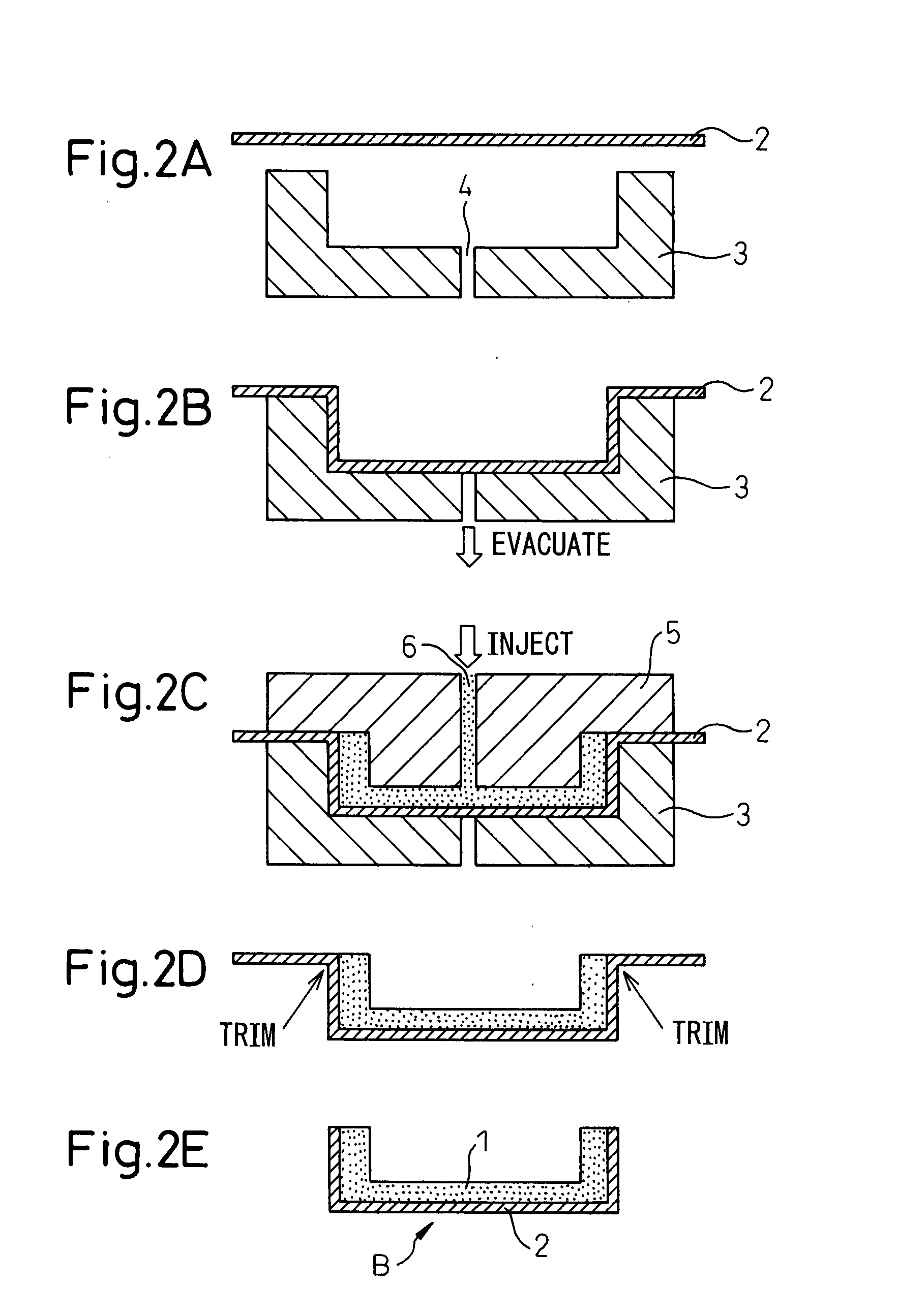
[0037]Further, according to the thermoplastic resin casing fabrication method of the present invention, a film having a polarizing effect is placed on a mold having a recess of a prescribed shape and is formed into the shape of the recess, and after the film is formed, an injection molding die is placed onto the mold with the film interposed therebetween, and a thermoplastic resin is injected into a recess formed by the film, thereby forming the thermoplastic resin casing. In this way, not only can a thin film be bonded flatly without creasing over the surface of the casing, but when removing the excess portion of the film, since the remaining edge portion of the film is secured to the thermoplastic resin by fusing, that is, since the edge portion of the film is secured to the thermoplastic resin body by embedding a portion of the film into the thermoplastic resin body when the thermoplastic resin body is injection-molded, or since the edge portion of the film is secured to the thermoplastic resin body by being embedded into the surface of the thermoplastic resin body when the thermoplastic resin body is injection-molded, the edge portion of the film laminated to the surface of the casing is not jagged after the excess portion of the film is removed, and the appearance of the thermoplastic resin casing can thus be enhanced.
[0038]In this way, according to the present invention, not only can the casing be easily fabricated by conferring the depth and three-dimensional effects and by providing special effects, such as smoothly changing iridescent color effects that cannot be rendered to the casing by such techniques as colored resin, painting, plating, evaporation, etc., but a fabrication method can be provided that is effective in improving the finished quality of the casing and prevent the formation of jagged edges at the edge portion of the casing.

Problems solved by technology

However, creating images to be reproduced, in particular, in white light by using the principle of holography requires a sophisticated technique and increases fabrication costs, and therefore, a method that uses holography is not a suitable method for fabricating inexpensive casings.
In the above decoration method, a polarizing film or plate pieces are attached to the exterior or interior surface of the casing, which is a tedious and time-consuming process to decorate the casing, and it is not possible to cover the entire exterior or interior surface of the casing.
As a result, if the pieces are attached to polygonal or curved surfaces of a casing, the decorative effect does not extend over the entire surface of the casing, and the effect is thus limited.
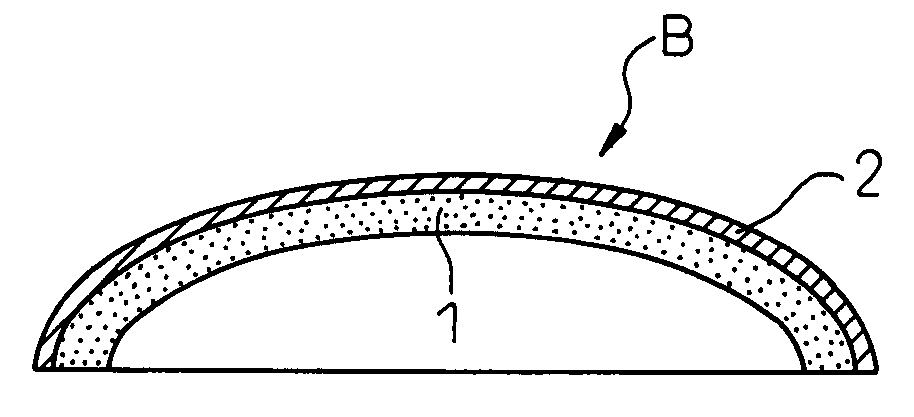
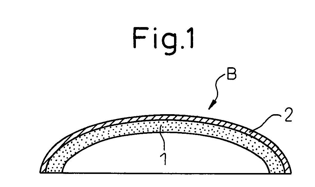
However, in the case of casing B shown in FIG. 1 in which a curved surface such as described by a three-dimensional curve is formed along the entire circumference of the protruding portion, it is difficult to bond a single polarizing film flatly along the curved surface without creasing over the entire surface of the protruding portion.
If the polarizing film is to be bonded only to a flat surface portion of casing B, the polarizing film can be bonded without creasing, but if the flat surface portion has a protruding portion formed thereon, it is difficult to bond the polarizing film flatly without creasing over the surface of the protruding portion.
Compared with this decorative film, the previously described polarizing film is thin and does not have a thickness suitable for such preforming, and therefore, the above fabrication method cannot be used in applications where a decorative effect is provided by attaching a polarizing film.
However, in the case of a molding formed from a thermoplastic resin, these molding fabrication methods for enhancing the appearance of the outer edge of the molding cannot be directly used.
However, in the molding fabrication method proposed above, the molding formed from the thermoplastic resin is trimmed at its outer edge, while the decorative film cut at its outer edge is bonded to the thermoplastic resin, the endmost portion of the decorative film may partially delaminate and become jagged, depending on the handling of the molding or due to the chafing of the outer edge during use.
As a result, while the decorative film can be bonded flatly without creasing over the surface of the molding, there arises a problem that the appearance of the molding as a whole degrades.

Method used


Image

  • Thermoplastic resin casing and method for fabricating the same
  • Thermoplastic resin casing and method for fabricating the same
  • Thermoplastic resin casing and method for fabricating the same

Examples


first embodiment

[0075]FIG. 5 shows cross-sectional views illustrating processing steps in a specific example of the thermoplastic resin casing fabrication method according to the first embodiment. The thermoplastic resin casing fabrication method according to this specific example is based on the fabrication method shown in the flowchart of FIG. 3, and FIG. 5A shows the condition corresponding to the fabrication step shown in FIG. 4A.

[0076]The fabrication method according to the specific example of the first embodiment shown in FIG. 5A differs from the fabrication method shown in FIG. 4A in that while the cutting die 7 in the earlier described method has been used to simply cut off the excess portion of the polarizing film 2, the fabrication method hereinafter described uses a cutting die 71 having a built-in heater as indicated by a solid circle, and this cutting die 71 is used to cut off the excess portion of the polarizing film 2.

[0077]FIG. 6 shows a flowchart illustrating the sequence of proces...

second embodiment

[0087]The first embodiment described above has dealt with an example in which the excess portion of the polarizing film 2 is cut off at the outer edge of the thermoplastic resin casing, but in the thermoplastic resin casing fabrication method according to the second embodiment hereinafter described, the excess portion of the polarizing film is cut off at a position spaced a prescribed distance away from the edge of the casing, allowing the edge portion of the polarizing film to extend beyond the edge of the casing, and the extended portion of the film is bent inwardly at the edge of the casing at which the extended portion of the film is processed for fixing. The inward portion of the edge of the casing is a portion where no decoration is needed or a portion that is hidden from view when the casing is in use.

[0088]FIG. 8 shows a series of cross-sectional views illustrating a specific example of the thermoplastic resin casing fabrication method according to the second embodiment, and...

third embodiment

[0097]The thermoplastic resin casing fabrication methods according to the first and second embodiments described above have concerned the case where the thermoplastic resin casing is fabricated through two separate processes, that is, after completing the molding by simultaneously forming the polarizing film and the thermoplastic resin in the resin molding process P1, the molding is transferred to the trimming process P2 in which the excess portion of the polarizing film is cut off and the edge portion of the film is processed for fixing. In the thermoplastic resin casing fabrication method according to the third embodiment hereinafter described, the resin molding process P1 and the trimming process P2 are performed as a continuous process so that the polarizing film is processed for fixing at an intermediate step in the thermoplastic resin molding process.

[0098]FIG. 10A is a cross-sectional view showing a mold and an injection molding die used in one specific example of the thermop...


PUM

PropertyMeasurementUnit
heataaaaaaaaaa
pressureaaaaaaaaaa
shapeaaaaaaaaaa

Abstract

The present invention relates to a decoration technique for providing iridescent color effects or glittering luster effects to a resin casing by attaching a polarizing film in contact with a resin casing, and for finishing a cut-off edge portion of the polarizing film smooth. After forming the polarizing film on a mold having a prescribed shape, a thermoplastic resin is injected into the mold to produce a thermoplastic resin casing to which the polarizing film is firmly attached. When cutting off an excess portion of the polarizing film by using a cutting die, a heater built into the cutting die is energized, and the cut-off edge portion of the polarizing film is fused by the heating of the cutting die, thus fixing the edge portion to the thermoplastic resin.

Description

CROSS-REFERENCE TO RELATED APPLICATION[0001]This application claims the priority of Japanese Patent Application Number 2006-341784, filed on Dec. 19, 2006.BACKGROUND OF THE INVENTION[0002]1. Field of the Invention[0003]The present invention relates to a thermoplastic resin casing and a method for fabricating the same, and more particularly to a thermoplastic resin casing that has a three-dimensional structure having an outwardly protruding portion containing a curved surface, wherein a film having a decorative effect is laminated to a thermoplastic resin thereby providing a special decorative effect to the casing, and an edge portion of the thus laminated film is processed for fixing thereto, and a method for fabricating such a thermoplastic resin casing.[0004]2. Description of the Related Art[0005]Traditionally, a casing such as a container for holding an article therein or a case in which an electronic part is housed, or a casing such as a vehicle bumper, motorcycle cowl, helmet, ...

Claims


Application Information

Patent Timeline
Patent Type & Authority Applications(United States)
IPC IPC(8): B32B1/04B29C45/00B32B1/00
CPCB29C45/1418B29C45/14221B29C45/14778B29C2045/14188Y10T428/24777B29K2995/0034Y10T428/1352Y10T428/24628Y10T428/2419B29K2995/0026
Inventor YUBA, TAKASHIAKIEDA, SHINICHIROARITA, TAKASHI
Owner FUJITSU COMPONENENT LTD
Learn More