Robot structure

a robot and structure technology, applied in the field of robot structure, can solve the problems of poor resolution of contact force and gripping force of the movable robot element, inability to use sensor elements in commercial instruments, and inability to measure the gripping force at a very high resolution, so as to improve the measurement of the force occurring

Inactive Publication Date: 2008-06-19
DEUTSCHES ZENTRUM FUER LUFT & RAUMFAHRT EV
View PDF8 Cites 37 Cited by
  • Summary
  • Abstract
  • Description
  • Claims
  • Application Information

AI Technical Summary

Benefits of technology

[0010]It is an object of the present invention to provide a robot structure, wherein the measurement of the forces occurring is improved, independent of driving and motional forces.

Problems solved by technology

Presently, such sensor elements are not employed in commercial instruments because of the measurement inaccuracies occurring.
It is a general problem that the contact forces and the gripping forces of the movable robot element can be measured only at a very poor resolution, since the forces occurring are superposed by substantially greater driving or motional forces of the force transmission means acting on the movable robot element.
However, the measurement of the gripping force is relatively inaccurate.
This instrument, described in G. Tholey, A Pillarisetti, W. Green and J. Desai, “Design, Development and Testing of an Automated Laparoscopic Grasper with 3D Force Measurement Capability”, Medical Simulation: International Symposium, ISMS 2004, has a drawback, however, in that only little structural space is available for the integration of sensors, since, especially in minimally invasive surgery, the gripping jaws have to be as small as possible.
This causes an impairment of the measurement results.
Therefore, the influence on the support may vary and can not, or only insufficiently, be compensated mathematically.

Method used


Image

  • Robot structure
  • Robot structure
  • Robot structure

Examples


Embodiment Construction

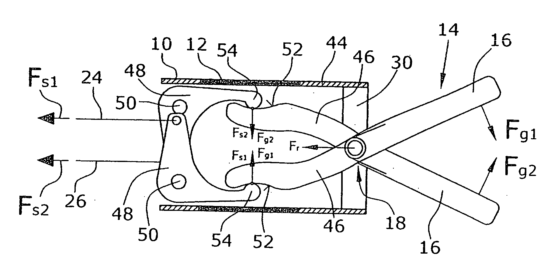
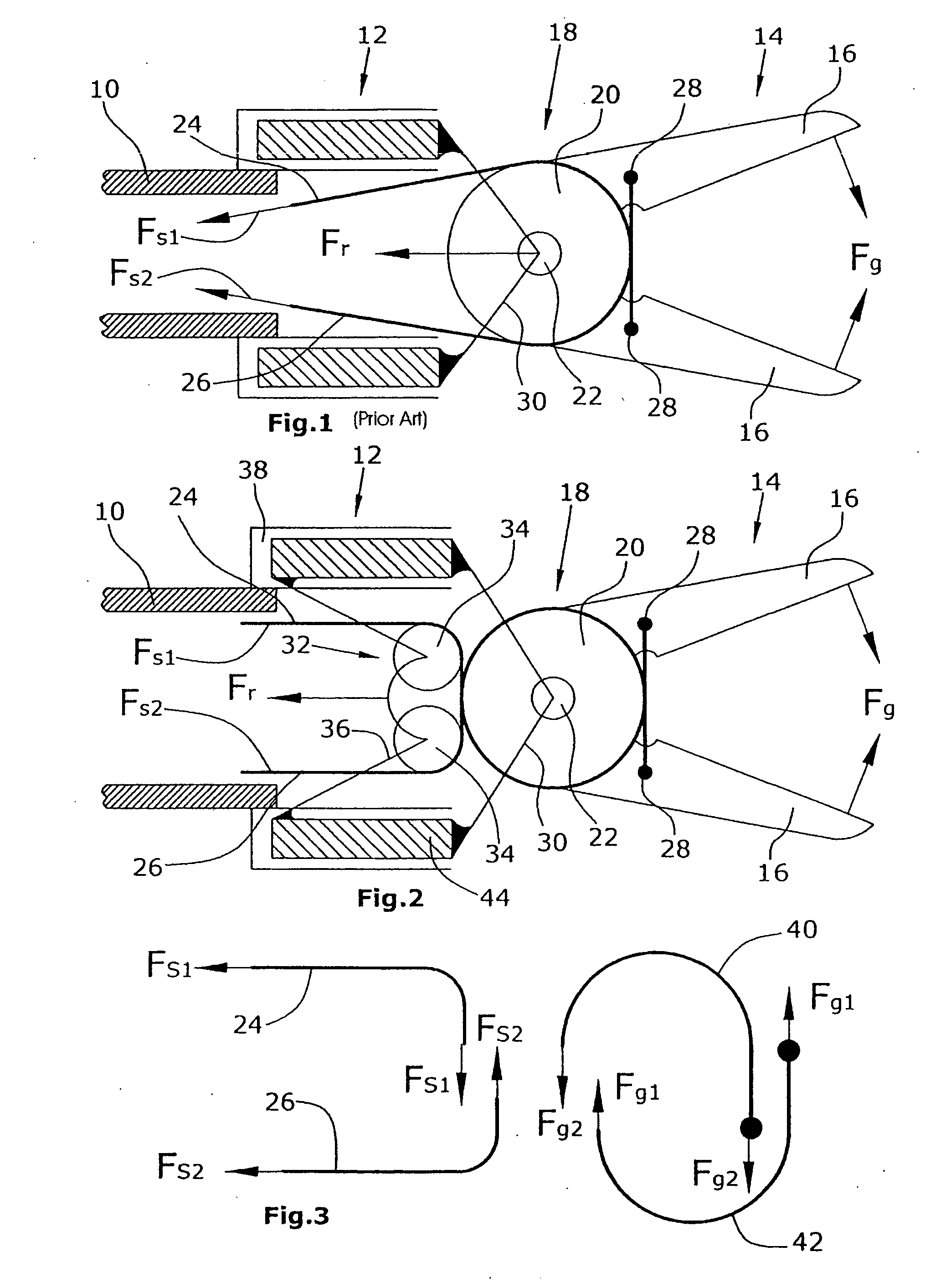
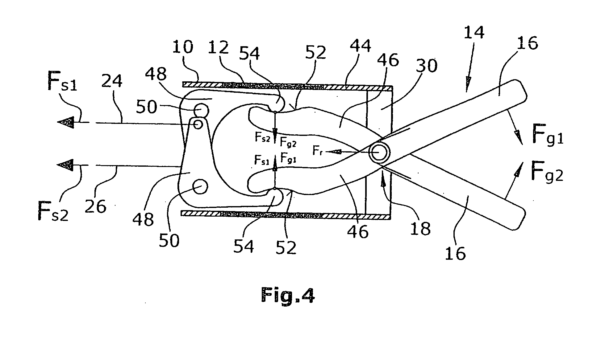
[0025]In prior art (FIG. 1), a sensor 12, such as a force / moment sensor, is rigidly connected to the first robot element 10. A second robot element 14 which in the present embodiment comprises two gripping elements 16 movable towards each other, is connected with the robot element 10 via a hinge 18. The robot element 14 may thus be moved relative to the robot element 10, wherein, in the prior art embodiment illustrated, the movement is carried out as a gripping or cutting by means of the gripping elements 16.

[0026]In the embodiment illustrated, the two gripping elements 16 are each rigidly connected with a pulley 20 arranged one behind the other, both pulleys 20 being pivotable about a common axis 22.

[0027]A force transmission means comprises two cables 24, 26 for actuating the gripping elements 16. The cable 24 is guided around the first pulley 20 to the lower gripping element 16 in FIG. 1 and is connected with the gripping element 16 by means of a fixing element 28. The second cab...


PUM


Abstract

A robot structure, suited especially for minimally invasive surgery, comprises two robot elements interconnected by a hinge. Using a force transmission means the movable robot element of said robot element, notably comprising two gripping elements, can be moved. A sensor element is provided for picking up forces occurring. To reduce the influence of motional forces, said force transmission means is connected with a base element of said sensor element such that motional forces transmitted by said force transmission element are supported at the base element.

Description

RELATED FOREIGN APPLICATION[0001]The present application claims the priority of the German Patent Application No. 10 2006 069 952.7 of Dec. 19, 2006, the disclosure of which is herewith incorporated herein by reference.BACKGROUND OF THE INVENTION[0002]1. Field of the Invention[0003]The present invention relates to a robot structure, notably for minimally invasive surgery.[0004]2. Description of Related Art[0005]In robot assisted minimally invasive surgery instruments, such as gripping or cutting instruments, are provided at the distal end of a robot structure. During a surgical operation, the instruments are located within a patient's body. To be able to operate and move the instruments connected with the robot structure, the robot structure has at least two robot elements interconnected via a hinge or a plurality of joints. Here, a first robot element may be designed as a robot arm and the second, movable robot element comprises at least two gripping elements that are movable again...

Claims


Application Information

Patent Timeline
Patent Type & Authority Applications(United States)
IPC IPC(8): A61B19/00
CPCA61B19/22A61B19/2203A61B2017/2933A61B2017/2934B25J15/0206A61B2019/2242A61B2019/464B25J13/082A61B2017/2939A61B2090/064A61B34/70A61B34/71A61B34/30
Inventor SEIBOLD, ULRICHHAGN, ULRICH ALEXANDERSTURM, MATTHIAS
Owner DEUTSCHES ZENTRUM FUER LUFT & RAUMFAHRT EV
Why Eureka
Try Eureka