Buckling disc replacement

a technology for discs and spines, applied in the field of spinal disc replacement methods and devices, can solve problems such as wear levels, range of motion, and changes in discs, discs, joints and ligaments of the body, and achieve the effects of improving function, improving function, and improving function

Active Publication Date: 2008-06-19
DEPUY SYNTHES PROD INC
View PDF110 Cites 45 Cited by
  • Summary
  • Abstract
  • Description
  • Claims
  • Application Information

AI Technical Summary

Benefits of technology

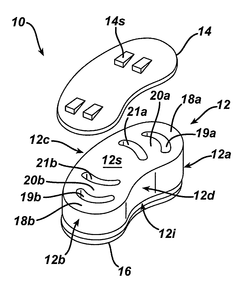
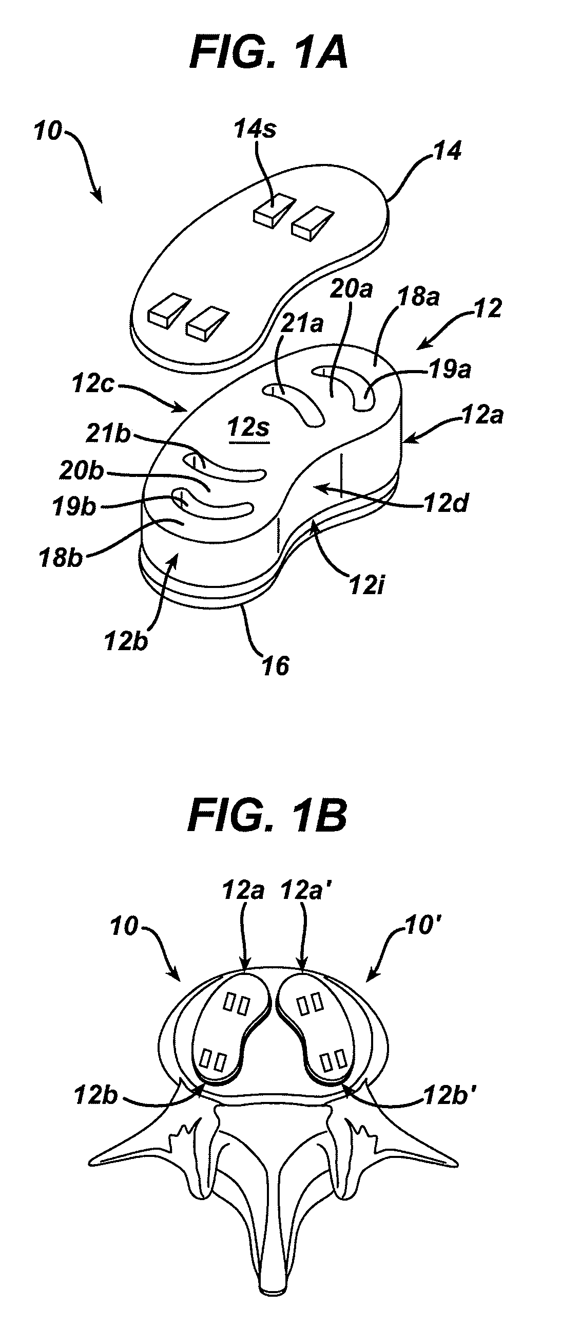
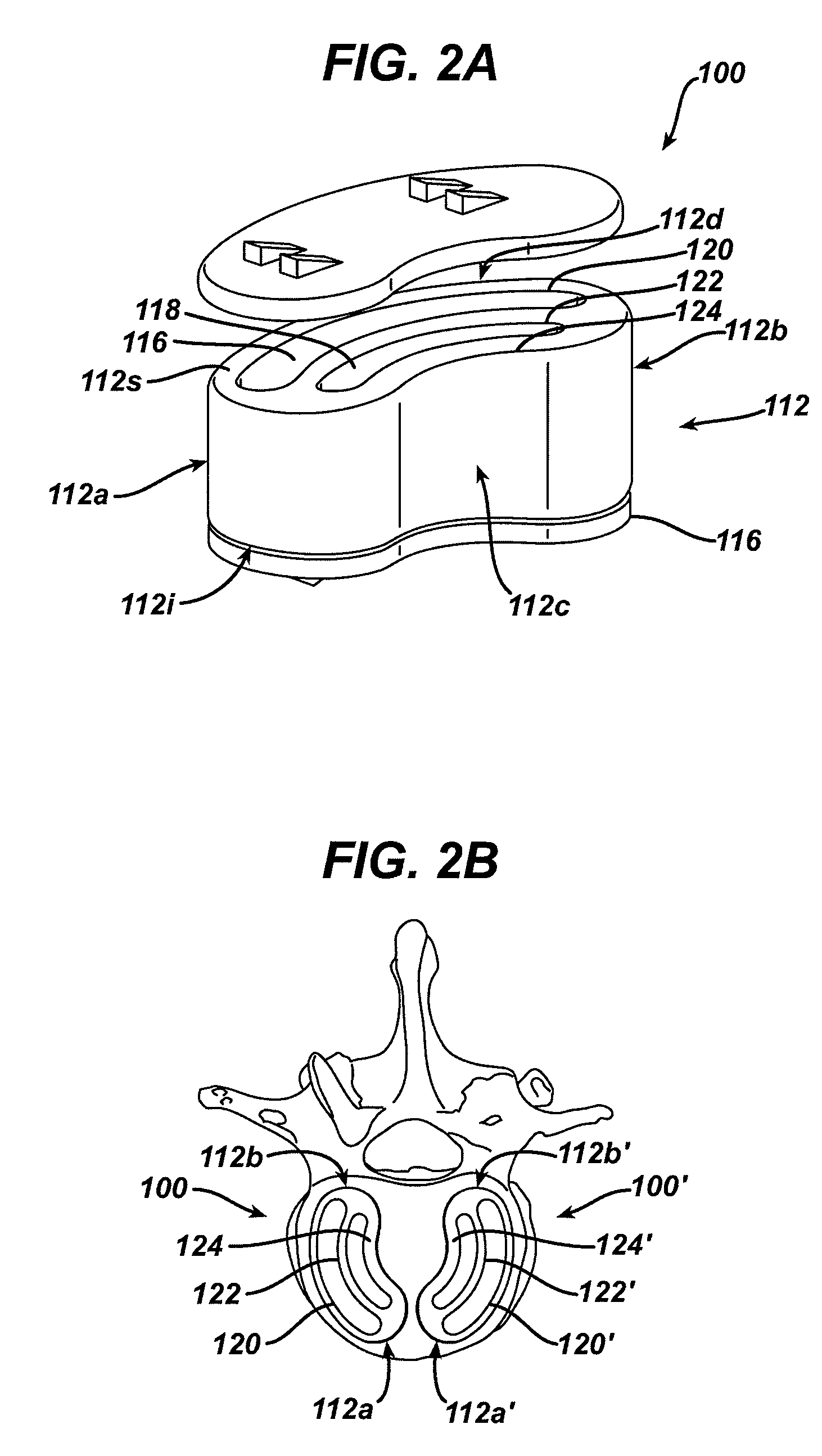
[0008]The implant can include any number of opening having various configurations. In one embodiment, the opening can extend between superior and inferior surfaces of the implantable body. In another embodiment, the implant can include a first opening positioned adjacent to a first terminal end wall of the implantable body, and a second opening positioned adjacent to a second opposite terminal end wall of the implantable body. The first and second terminal end walls of the implantable body can be adapted to buckle in response to movement of adjacent vertebrae when implanted therebetween. The implant can also include a third opening extending through the implantable body adjacent to the first opening such that the implantable body includes a first inner wall extending between the first and third openings, and a fourth opening extending through the implantable body adjacent to the second opening such that the implantable body includes a second inner wall extending between the second and fourth openings. The first and second inner walls can be adapted to buckle in response to movement of adjacent vertebrae when implanted therebetween. In yet another embodiment, the first and second terminal end walls of the implantable body can have a buckling strength that is less than a buckling strength of the first and second inner walls such that the first and second terminal end walls will buckle before the first and second inner walls buckle in response to movement of adjacent vertebrae when implanted therebetween. In other aspects, the implant can include a plurality of axially-extending openings defining a plurality of axially-extending posts. At least one of the posts can have a geometry that differs from a geometry of at least another one of the posts such that at least one of the posts has a buckling strength that is less than a buckling strength of another one of the posts.
[0009]Exemplary methods for controlling movement between adjacent vertebrae of a spine are also provided. In one embodiment, the method can include positioning an elastomeric implant between adjacent vertebrae such that at least one wall extending through the implant extends between opposed endplates of the adjacent vertebrae and the at least one wall buckles in response to movement of adjacent vertebrae to thereby control movement between the adjacent vertebrae. In an exemplary embodiment, the wall(s) is positioned to buckle in response to at least one of flexion, extension, and lateral bending of the adjacent vertebrae. The implant can have a variety of configurations. For example, the elastomeric implant can include a first half positioned on a first lateral side of a disc space formed between the adjacent vertebrae, and a separate second half positioned on a second opposite lateral side of the disc space. In another embodiment, the elastomeric implant can be positioned between first and second endplate members that are positioned adjacent to the opposed endplates of the adjacent vertebrae. The method can also include, prior to positioning the elastomeric implant, introducing the implant using one or a posterior surgical approach, a postereo-lateral surgical approach, an anterior surgical approach, and an antereo-lateral surgical approach.

Problems solved by technology

Disease, advancing age, and trauma can lead to changes in various bones, discs, joints, and ligaments of the body.
This condition often results in chronic back pain, which can be anywhere from mild to severe.
While many of the current designs are successful, some of the challenges with current designs include wear levels, fatigue under loading, range of motion, and surgical window size required to implant the disc replacement.

Method used


Image

  • Buckling disc replacement
  • Buckling disc replacement
  • Buckling disc replacement

Examples


Embodiment Construction

[0024]Certain exemplary embodiments will now be described to provide an overall understanding of the principles of the structure, function, manufacture, and use of the devices and methods disclosed herein. One or more examples of these embodiments are illustrated in the accompanying drawings. Those of ordinary skill in the art will understand that the devices and methods specifically described herein and illustrated in the accompanying drawings are non-limiting exemplary embodiments and that the scope of the present invention is defined solely by the claims. The features illustrated or described in connection with one exemplary embodiment may be combined with the features of other embodiments. Such modifications and variations are intended to be included within the scope of the present invention.

[0025]The present invention generally provides devices and methods for replacing a spinal disc, and in particular devices and methods that rely on buckling to control movement of adjacent ve...


PUM


Abstract

Devices and methods are provided for replacing a spinal disc, and in particular devices and methods are provided that rely on buckling to control movement of adjacent vertebrae. In one embodiment, an artificial disc replacement implant is provided and includes an implantable body having a superior surface adapted to be positioned adjacent to an endplate of a superior vertebra, and an opposite inferior surface adapted to be positioned adjacent to an endplate of an adjacent inferior vertebrae. The implantable body includes at least one wall formed therein and extending between the superior and inferior surfaces. The wall(s) can be adapted such that, when the implantable body is disposed between the endplates of adjacent superior and inferior vertebrae, the wall(s) will buckle by moving laterally and shorting in height under a load applied thereto by movement of the adjacent vertebrae. The implantable body can also include at least one opening formed adjacent to the wall(s) and extending between the superior and inferior surfaces of the implantable body.

Description

FIELD OF THE INVENTION[0001]The present invention relates to methods and devices for replacing a spinal disc.BACKGROUND OF THE INVENTION[0002]Disease, advancing age, and trauma can lead to changes in various bones, discs, joints, and ligaments of the body. Some changes and trauma often manifest themselves in the form of damage or degeneration to a spinal disc. This condition often results in chronic back pain, which can be anywhere from mild to severe. This pain can sometimes be eliminated by spinal fusion in which two adjacent vertebral bodies are jointed together after removing the intervening intervertebral disc. A prosthetic device is usually placed between the two adjacent vertebral bodies, in place of the removed disc, to fill the space left by the removed disc and to allow bone to grow between the two vertebral bodies.[0003]More recently, spinal disc replacement implants have been developed that allow motion between the adjacent vertebrae, thereby restoring normal function to...

Claims


Application Information

Patent Timeline
Patent Type & Authority Applications(United States)
IPC IPC(8): A61F2/44
CPCA61F2/442A61F2002/30131A61F2002/30156A61F2002/30224A61F2002/30232A61F2230/0069A61F2002/30904A61F2002/4475A61F2002/448A61F2230/0013A61F2230/0023A61F2002/30563A61F2002/30593
Inventor LOPEZ, ERASMOKWAK, SEUNGKYU DANIELBORGSTROM, AMIEHAWKINS, JOHN R.
Owner DEPUY SYNTHES PROD INC
Why Eureka
Try Eureka