
Prosthetic vacuum system

a vacuum system and prosthetic technology, applied in the field of prosthetic vacuum systems, can solve the problems of amputees that cannot use this system, size and weight, and the inability to use the suction socket on the below-knee amputees, and achieve the effects of reducing the cycle of vacuum pumps, reducing the number of users, and facilitating use for most amputees

Active Publication Date: 2008-06-19
OSSUR ICELAND EHF +1
View PDF31 Cites 64 Cited by
  • Summary
  • Abstract
  • Description
  • Claims
  • Application Information

AI Technical Summary

Benefits of technology

[0010]Unlike the foregoing devices which teach systems that are difficult, if not impossible, for some amputees to use because of their bulk, the nature of the amputation, or size of the individual, which interferes with and limits a user's capability to use the advantages of a secure attachment of the artificial limb. The current invention provides a lightweight, small and concealable vacuum system that is easier for most amputees to use and less tiring to the user. The aesthetic advantages are apparent. The system can be securely concealed in the prosthetic device, principally in a shoe insert or in the leg pipe itself. This allows the limb to be more attractive and available for all size and age users. Thus, it can be used in the widest range of amputees—both below and above the knee.
[0011]The incorporation of a concealable vacuum surge chamber connected to the negative pressure environment in the cavity between the socket of the prosthetic device and the residual limb allows the vacuum to be maintained for longer periods of time, thus reducing vacuum pump cycling, which in turn allows for longer use of the battery be...

Problems solved by technology

Use of suction sockets on below knee amputees were not initially practical.
The disadvantages of this system are size and weight.
There are many amputees that cannot use this system because of size, age, length of the stump and of course children.
The entire system is in a large box that is strapped to the artificial limb, it lacks a surge chamber and is too large to be cosmetically acceptable.
The disadvantages of the Smith system include short battery life because of the constant need to regain an acceptable vacuum level.

Method used


Image

  • Prosthetic vacuum system
  • Prosthetic vacuum system
  • Prosthetic vacuum system

Examples


Embodiment Construction

[0031]In the following description, specific details are set forth in order to provide a thorough understanding of the invention. However, it will be apparent that the invention may be practiced without these specific details.

[0032]Without departing from the generality of the invention disclosed herein and without limiting the scope of the invention, the discussion that follows, will refer to the invention as depicted in the drawing.

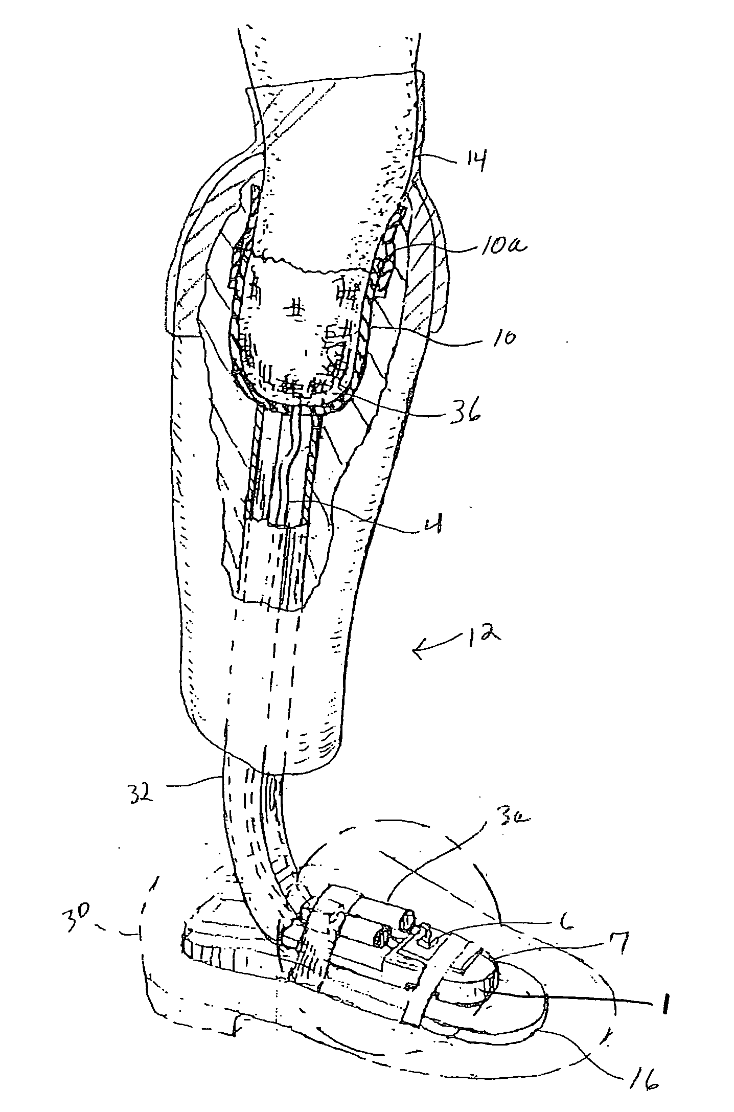
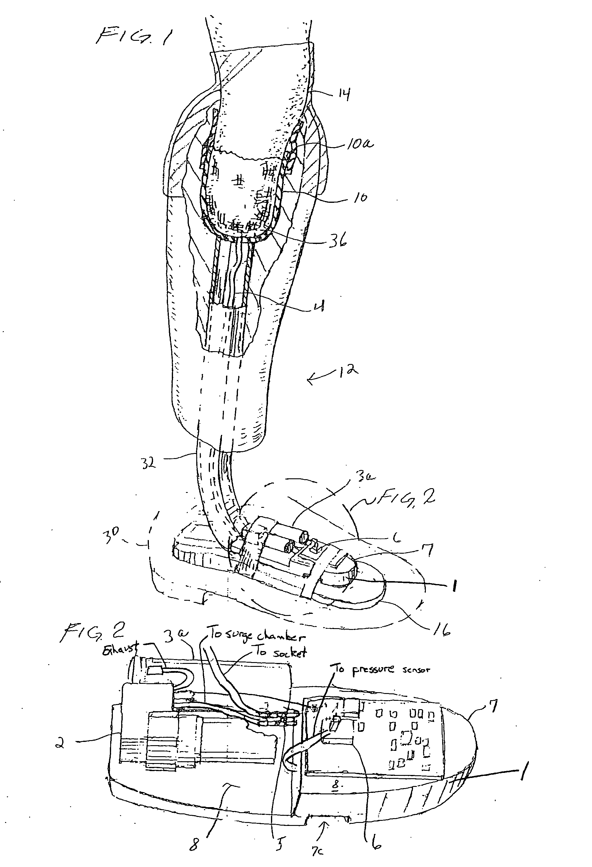
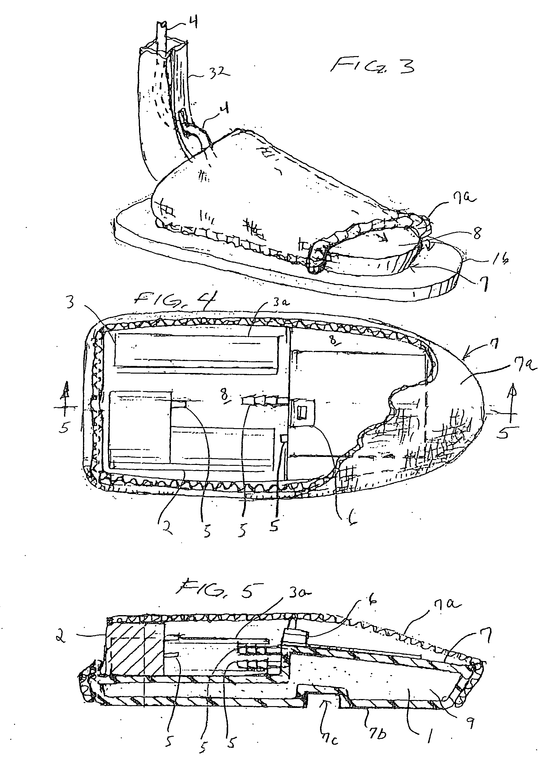
[0033]According to one embodiment, a vacuum system for maintaining a negative pressure in a cavity 36 between a socket 10 of a prosthetic device 12 and a residual limb 14 on which the prosthetic device is attached. The vacuum system comprises a concealable vacuum surge chamber 1, a vacuum pump 2, a power source 3, tubing 4, tubing connectors 5, and means for sensing pressure and actuating the system, in which the cavity 36 is operatively connected to the surge chamber 1 and the vacuum pump 2 with the tubing 4 and tubing connectors 5 and the means for sen...


PUM


Abstract

An improved prosthetic device with a vacuum system for maintaining a negative pressure seal between the socket and the residual limb. The vacuum system includes a vacuum surge chamber which maintains seal vacuum and increases battery life. The system is small, lightweight, and concealable within the prosthetic device so that it neither impedes use of the device nor detracts from a cosmetically accurate limb.

Description

BACKGROUND OF THE INVENTION[0001]The history of artificial limbs begins with very remote times. There is some evidence that the Romans and the Greeks improvised some sort of substitute for the limbs lost in battle and the vicissitudes of life. Herodotus tells us of a prisoner who amputated his own foot in order to free himself from the shackle, after which he escaped and returned to his friends, who made a wooden foot.[0002]The treasure trove that turned up at Capua in 1885 in a tufa tomb is probably the most valuable and indisputable evidence that artificial legs were made in early times. The relic is now on exhibition in the Museum of the Royal College of Surgeons, London. The official catalogue describes it thus: “Roman artificial leg; the artificial limb accurately represents the form of the leg. It is made with pieces of thin bronze, fastened by bronze nails to a wooden core. Two iron bars, having holes at their free ends, are attached to the upper extremity of the bronze. A qu...

Claims


Application Information

Patent Timeline
IPC IPC(8): A61F2/72A61F2/80A43B13/38
CPCA61F2/68A61F2/78A61F2002/5001A61F2002/6614A61F2002/701A61F2002/704A61F2002/807A61F2002/747A61F2002/7635A61F2002/7655A61F2002/768A61F2002/802A61F2002/742A61F2/70A61F2/74A61F2/742
Inventor DANZIG, MORRIS J.BUSH, HARRY DAVIDMCKINNEY, DONALD RAY
Owner OSSUR ICELAND EHF
Learn More