
Control System for the Conversion of Carbonaceous Feedstock into Gas

a technology of carbonaceous feedstock and control system, which is applied in the direction of functional valve types, magnetic recording, element comparison, etc., can solve the problems of insufficient treatment of prior systems and processes, less desirable disposal of waste materials by incineration, etc., and achieve the effect of fast response to deviation

Active Publication Date: 2008-06-19
PLASCO CONVERSION TECH INC
View PDF99 Cites 121 Cited by
  • Summary
  • Abstract
  • Description
  • Claims
  • Application Information

AI Technical Summary

Benefits of technology

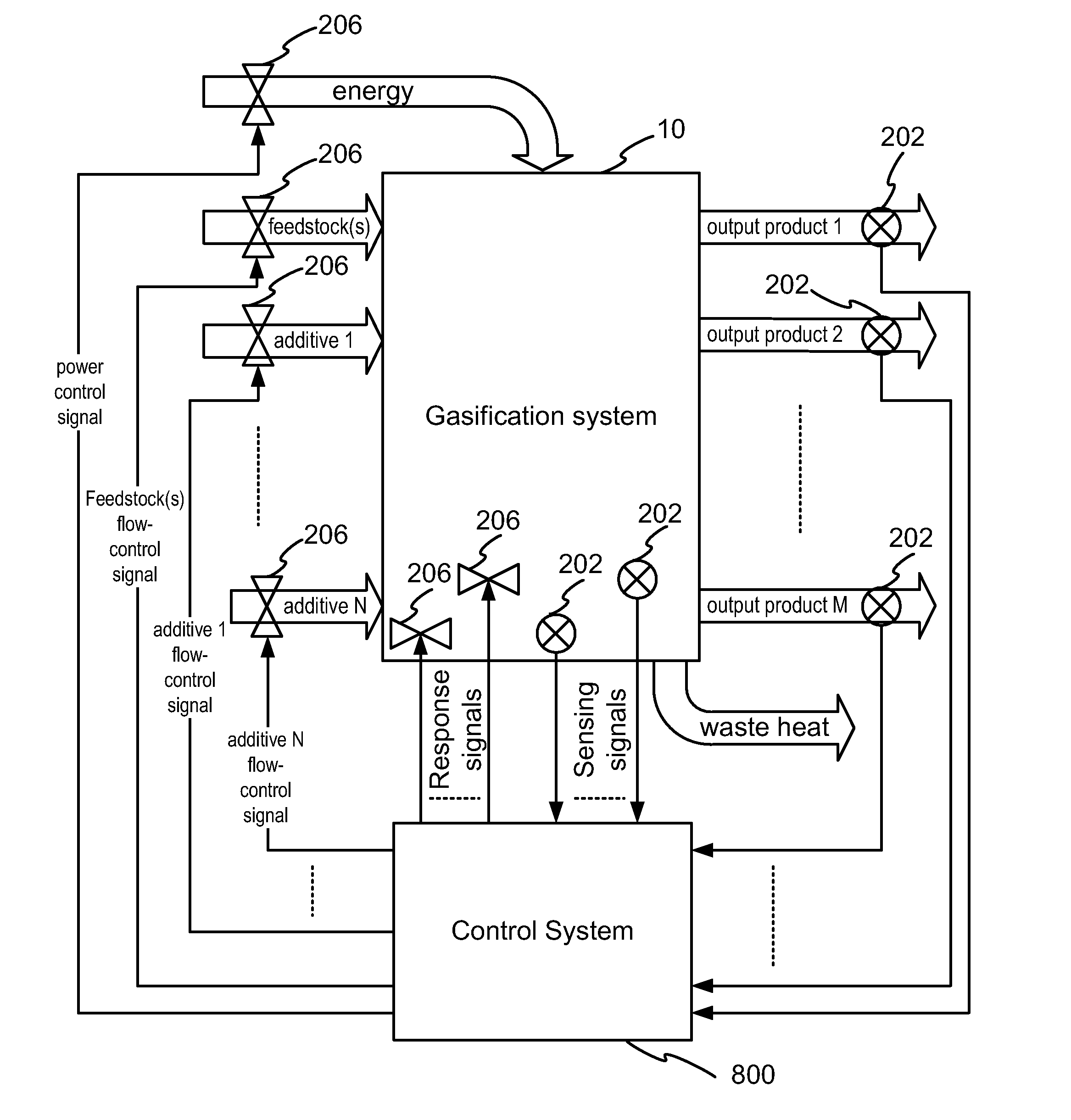
[0022]An object of the present invention is to provide a control system for the conversion of carbonaceous feedstock into gas. In accordance with one aspect of the present invention, there is provided a control system for use in controlling a gasification process for converting a carbonaceous feedstock into a gas suitable for use in a selected downstream application, the system comprising: one or more sensing elements for sensing one or more characteristics of the gas; one or more computing platforms communicatively linked to said one or more sensing elements for accessing a characteristic value representative of said sensed one or more characteristics; comparing said characteristic value with a predetermined range of such values defined to characterise the gas as suitable for the selected downstream application; and computing one or more process control parameters conducive to maintaining said characteristic value within said predetermined range; and a plurality of response elements operatively linked to one or more process devices operable to affect the process and thereby adjust said one or more characteristics of the gas, and communicatively linked to said one or more computing platforms for accessing said one or more computed process control parameters and operating said one or more process devices in accordance therewith.

Problems solved by technology

It is becoming less desirable to dispose of waste material by incineration because of the extreme waste of fuel in the heating process and the further waste of disposing, as a residual waste, material that can be converted into a useful syngas and solid material.
The gas produced during the gasification of carbonaceous feedstock is usually very hot but may contain small amounts of unwanted compounds and requires further treatment to convert it into a useable product.
Prior systems and processes have not adequately addressed the problems that must be dealt with on a continuously changing basis.

Method used


Image

  • Control System for the Conversion of Carbonaceous Feedstock into Gas
  • Control System for the Conversion of Carbonaceous Feedstock into Gas
  • Control System for the Conversion of Carbonaceous Feedstock into Gas

Examples


example 1

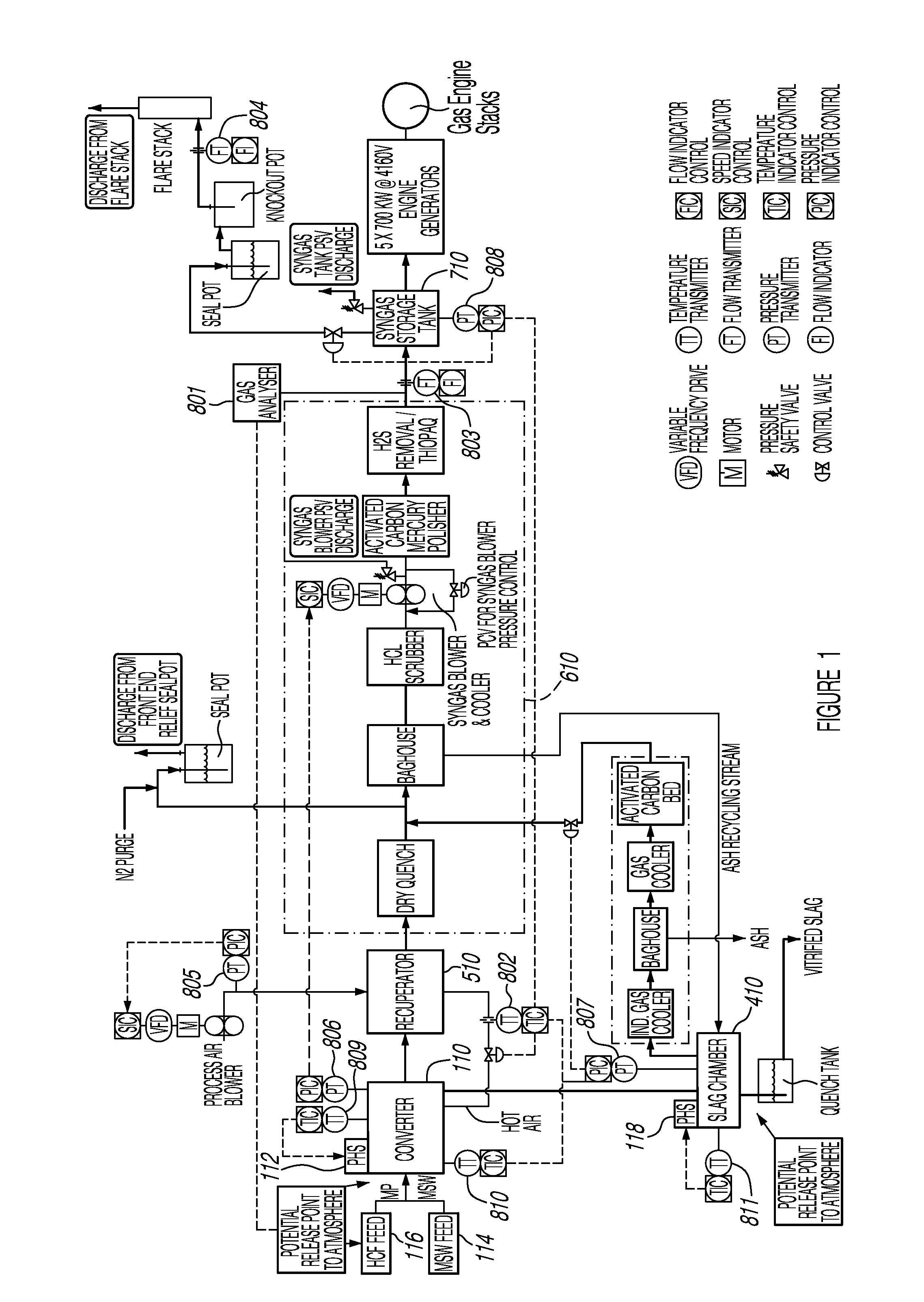
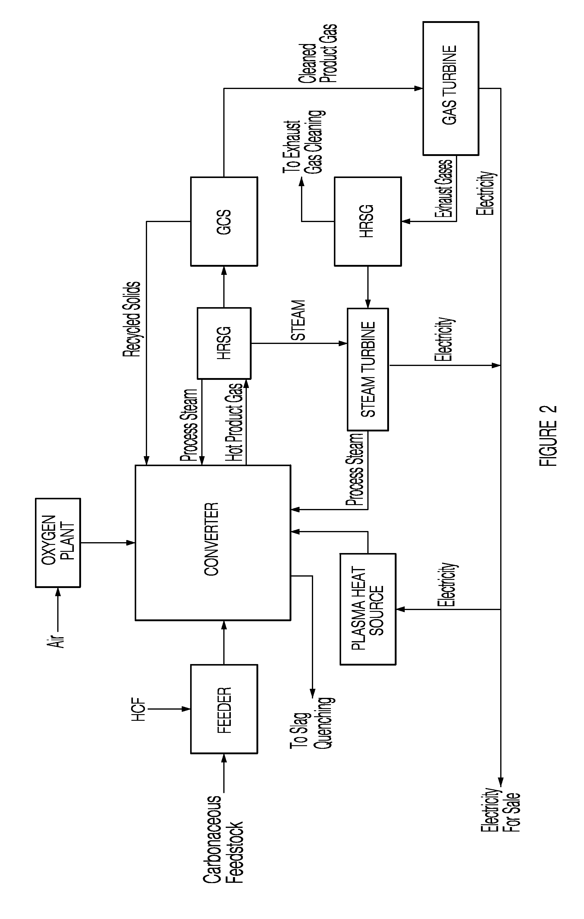
[0328]In this example, with reference to FIGS. 27 to 72, details of one exemplary embodiment of the invention, including various options, are provided. This example presents details for each subsystem of a gasification system amenable for use with the control system of the present invention and demonstrates how they work together to function as an integrated system for the conversion of municipal solid waste (MSW) into electricity. The subsystems discussed in this example are: a Municipal Solid Waste Handling System; a Plastics Handling System; a Horizontally Oriented Gasifier with Lateral Transfer Units System; a Gas Reformulating System; a Heat Recycling System; a Gas Conditioning System; a Residue Conditioning System and a Gas Homogenization System.

[0329]FIG. 1 shows a functional block diagram overview of the entire gasification system 120, amenable for use with the control system of the present invention, designed primarily for the conversion of MSW to syngas, with the associate...

example 2

[0536]In this example an alternative control scheme is presented for a gasification system such as the one presented in Example 1. This alternative control scheme is presented in FIG. 73 and is a variant of the control scheme presented in FIG. 71, wherein a syngas pressure detection module is used instead of a syngas flow detection module.

example 3

[0537]In this example an alternative control scheme is presented for a gasification system such as the one presented in Example 1. FIG. 74 provides an alternative control flow diagram depicting the various sensed characteristic values, controllers (e.g. response elements) and operating parameters used by the control system 8000 of the present example, and interactions therebetween conducive to promoting proper and efficient processing of the feedstock. In this example:[0538]a converter solids levels detection module 8550 is configured to cooperatively control a transfer unit controller 8552 configured to control motion of the transfer unit(s) 8554 and cooperatively control a total MSW+HCF feed rate 8556;[0539]a syngas (product gas) carbon content detection module 8558 (e.g. derived from a gas analyser) is operatively coupled to a MSW:HCF ratio controller 8560 configured to cooperatively control the total MSW+HCF feed rate 8556 for controlling an MSW / HCF splitter 8562 (for controllin...


PUM

PropertyMeasurementUnit
Temperatureaaaaaaaaaa
Fractionaaaaaaaaaa

Abstract

The present invention provides a control system for the conversion of carbonaceous feedstock into a gas. In particular, the control system is designed to be configurable for use in controlling one or more processes implemented in, and / or by, a gasification system for the conversion of such feedstock into a gas, which may be used for one or more downstream applications. Gasification processes controllable by different embodiments of the disclosed control system may include in various combinations, a converter, a residue conditioner, a recuperator and / or heat exchanger system, one or more gas conditioners, a gas homogenization system and one or more downstream applications. The control system operatively controls various local, regional and / or global processes related to the overall gasification process, and thereby adjusts various control parameters thereof adapted to affect these processes for a selected result. Various sensing elements and response elements are therefore distributed throughout the controlled system and used to acquire various process, reactant and / or product characteristics, compare these characteristics to suitable ranges of such characteristics conducive to achieving the desired result, and respond by implementing changes to in one or more of the ongoing processes via one or more controllable process devices.

Description

CROSS REFERENCE TO RELATED APPLICATIONS[0001]This application claims benefit of priority under 35 U.S.C. §119(e) from U.S. Provisional Application Ser. No. 60 / 746,632, filed May 5, 2006. This application also claims benefit of priority to International Patent Application No. PCT / CA2006 / 000881, filed Jun. 5, 2006. This application also claims benefit of priority to International Patent Application No. PCT / CA2006 / 000882, filed Jun. 5, 2006. This application also claims benefit of priority under 35 U.S.C. §119(e) from U.S. Provisional Application Ser. No. 60 / 864,116, filed Nov. 2, 2006. This application also claims benefit of priority under 35 U.S.C. §119(e) from U.S. Provisional Application Ser. No. 60 / 911,179, filed Apr. 11, 2007. This application also claims benefit of priority under 35 U.S.C. §119(e) from U.S. Provisional Application Ser. No. 60 / 797,973, filed May 5, 2006. The contents of all of the aforementioned applications are hereby expressly incorporated by reference in their...

Claims


Application Information

Patent Timeline
IPC IPC(8): G05B15/02
CPCC10J3/00Y10T436/12C10J3/82C10J3/84C10J3/86C10J2300/0916C10J2300/092C10J2300/0923C10J2300/093C10J2300/0946C10J2300/0973C10J2300/1238C10J2300/1671C10J2300/1675C10J2300/1869C10J2300/1884C10J2300/1892C10K1/002C10K1/003C10K1/004C10K1/006C10K1/007C10K1/024C10K1/101C10K1/12C10K1/20C10K1/32Y02E20/18C10J3/723C03B5/005C03B5/025C10J2300/1603C10J3/002C10J2300/0956C10J2300/0976Y02P40/50G11B5/00C10J3/20
Inventor TSANGARIS, ANDREASSWAIN, MARGARET
Owner PLASCO CONVERSION TECH INC
Learn More