Fastening structure of clean container

a technology of fastening structure and clean container, which is applied in the direction of caps, instruments, applications, etc., can solve the problems of loss of function, inability to perform smoothly cleaning and drying of reticle box b>10/b>, and easy accumulation of particles, so as to reduce the number of fastening components and strengthen the clean container of elastic components

Inactive Publication Date: 2008-06-26
IND TECH RES INST
View PDF11 Cites 14 Cited by
  • Summary
  • Abstract
  • Description
  • Claims
  • Application Information

AI Technical Summary

Benefits of technology

[0009]In view of the disadvantages in the prior arts, the present invention is directed to providing a fastening structure. In the present invention, the number of fastening components is decreased,

Problems solved by technology

However, according to this design, because the force arm of the elastic arms 131 are long, and the torque endured by supporting points is large, when the elastic arm 131 is opened and closed repeatedly, and is easily broken or bent due to fatigue, thereby losing the function, the elastic pieces 13 must be replaced as a whole.
As a result, not only the particles will easily deposit in the dead angles between the elastic pieces 13 and the retaining plates 14, but also the operation of c

Method used


Image

  • Fastening structure of clean container
  • Fastening structure of clean container
  • Fastening structure of clean container

Examples


first embodiment

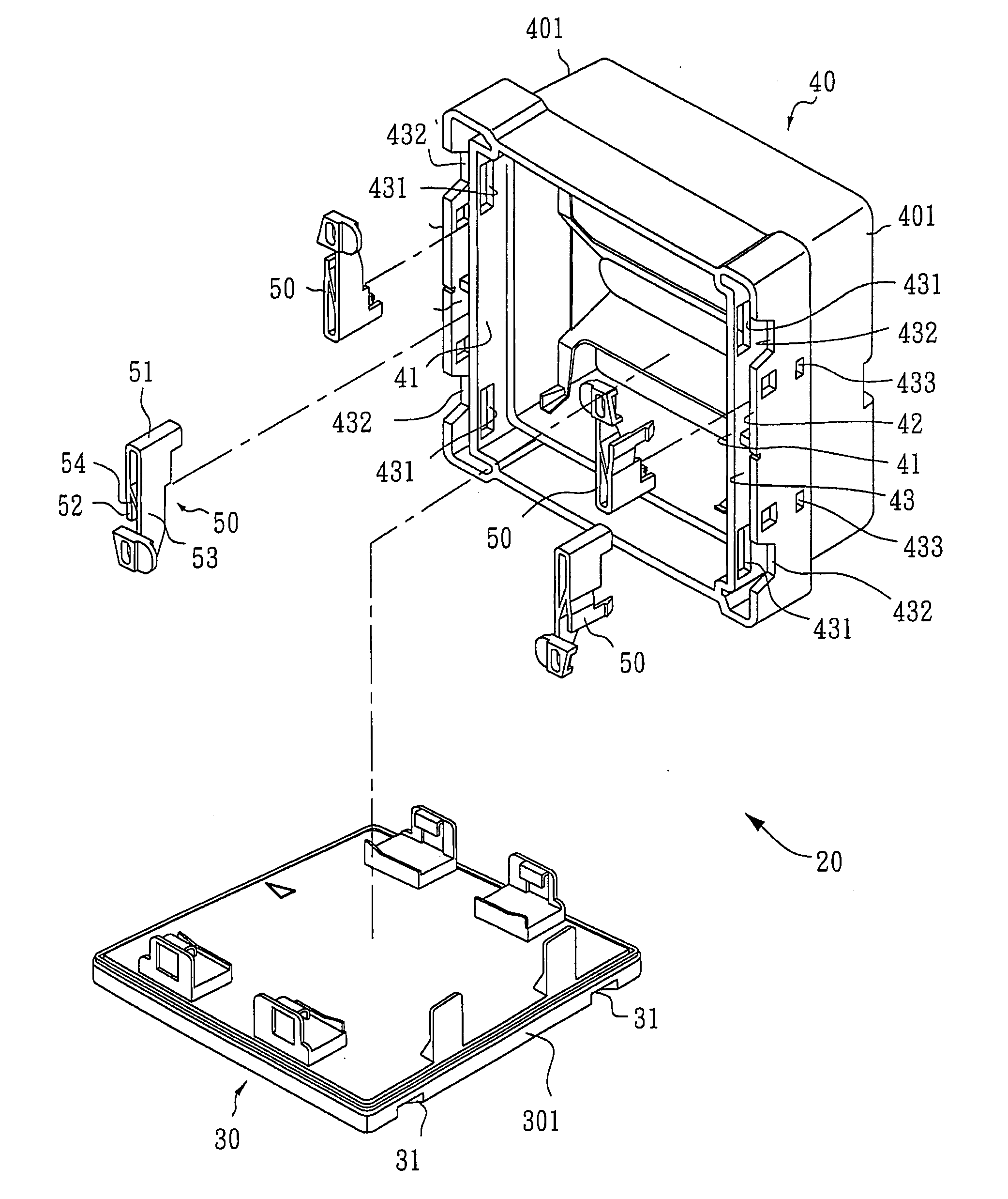
[0038]Firstly, FIG. 2 is an exploded isometric view of an embodiment of the fastening structure of the clean container according to the present invention; FIG. 3 is an exploded isometric view of the fastener member and the accommodation groove of the cover in FIG. 2; and FIG. 4 is an isometric view of the fastener member and the elastic auxiliary arm of the fastening structure of the clean container according to the present invention. The fastening structure of the clean container 20 in this embodiment of the present invention uses one or more fastener members 50, so as to be engaged removably and combined to a cover 40 of the clean container, such that the cover 40 can be fastened or opened on the base 30 of the clean container. The side face 301 of the outer frame of the base 30 has grooves 31 according to the number of the fastener members 50, a side face 401 of the cover 40 has an internal plate 41 and an external plate 42 extending outwards, so as to cover the outer frame of th...

second embodiment

[0046]In addition, FIGS. 10 to 15 are schematic views of the elastic auxiliary arm of the fastening structure of the clean container according to various embodiments of the present invention. As for the elastic auxiliary arm shown in FIG. 10, the elastic auxiliary arm 54a is perpendicular to the first frame 5111 (or the elastic arm 531) and the second frame 5112.

third embodiment

[0047]As for the elastic auxiliary arm shown in FIG. 11, the elastic auxiliary arm 54b has a first support arm 541b and a second support arm 542b formed between the first frame 5111 (or the elastic arm 531) and the second frame 5112, and the first support arm 541b and the second support arm 542b are approximately L-shaped structures, and are corresponding to each other.

[0048]As for a fourth embodiment of the elastic auxiliary arm shown in FIG. 12, the elastic auxiliary arm 54c is similar to the elastic auxiliary arm 54b of third embodiment in respect of the structure and connection relationship, while only the roots of the first support arm 541c and the second support arm 542c are reduced.


PUM


Abstract

A fastening structure of a clean container is combined on a cover of the clean container with a dismountable fastener member, such that the cover is closed or opened on a base of the clean container. The fastener member includes a body, a positioning portion, and an elastic fastening arm, that are one-piece formed. The positioning portion extends from one side of the body to form a flat spring. A flange is formed on the flat spring to fasten the fastener member on the cover. The elastic fastening arm has an elastic arm, and a lateral flange is formed on one end of the elastic arm, and extends into the base to be buckled. The fastener member further includes an elastic auxiliary arm formed between the elastic arm and the body, so as to increase an elastic strength of the elastic fastening arm.

Description

CROSS-REFERENCE TO RELATED APPLICATIONS[0001]This non-provisional application claims priority under 35 U.S.C. §119(a) on Patent Application No(s). 095148654 filed in Taiwan, R.O.C. on Dec. 22, 2006, the entire contents of which are hereby incorporated by reference.BACKGROUND OF THE INVENTION[0002]1. Field of Invention[0003]The present invention relates to a fastening structure of a container, and more particularly, to a self-locking fastening structure of a clean container applied in a clean room.[0004]2. Related Art[0005]To clean containers, such as mask storage boxes, reticle storage boxes, wafer storage boxes, or glass substrate storage boxes, masks, reticles, wafers, or glass substrates are usually placed therein, so as to meet the strigent requirements on an ultra-clean storage environment for accommodating the masks, reticles, wafers, or glass substrates used in a semiconductor or a flat panel display process, and to strictly prevent the masks, reticles, wafers, or glass subst...

Claims


Application Information

Patent Timeline
IPC IPC(8): B65D51/00B65D41/16
CPCG03F7/70741G03F1/66
Inventor WU, TZONG-MING
Owner IND TECH RES INST
Why Eureka
Try Eureka