

Insulating motor housing
a technology of motor housing and housing body, which is applied in the direction of supporting/enclosed/cases, dynamo-electric machines, structural associations, etc., can solve the problems of additional step of assembling terminals and resin plates in the housing body, burden to workers, and labor costs that are difficult to reduce, so as to achieve effective reduction of labor costs, easy supply, and effective reduction of burden to workers
- Summary
- Abstract
- Description
- Claims
- Application Information
AI Technical Summary
Benefits of technology
Problems solved by technology
Method used
Image

Examples
first embodiment
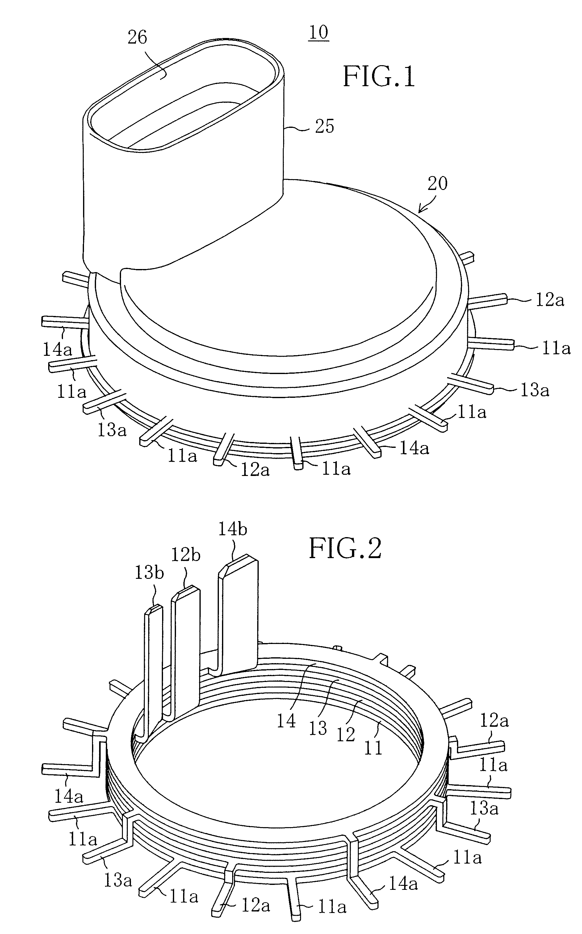
[0030]FIG. 1 is a perspective view illustrating the general structure of an insulating motor housing of a first embodiment of the present invention and FIG. 2 is a perspective view illustrating the structure of power supply elements of the insulating motor housing. As shown in FIGS. 1 and 2, an insulating motor housing 10 includes first to fourth power supply elements 11 to 14 which are made of flat conductive metal (e.g., copper) and provided with power source terminals 12b to 14b for connection to a power source and a plurality of coil terminals 11a to 14a for energizing motor coils and a resin housing body 20 for holding the first to fourth power supply elements 11 to 14.
[0031]The first power supply element 11 consists of a ring-shaped element and has a plurality of coil terminals 11a protruding radially outward from its outer rim.
[0032]The second to fourth power supply elements 12 to 14 also consist of ring-shaped elements, respectively, and are sequentially stacked to be spaced...
second embodiment
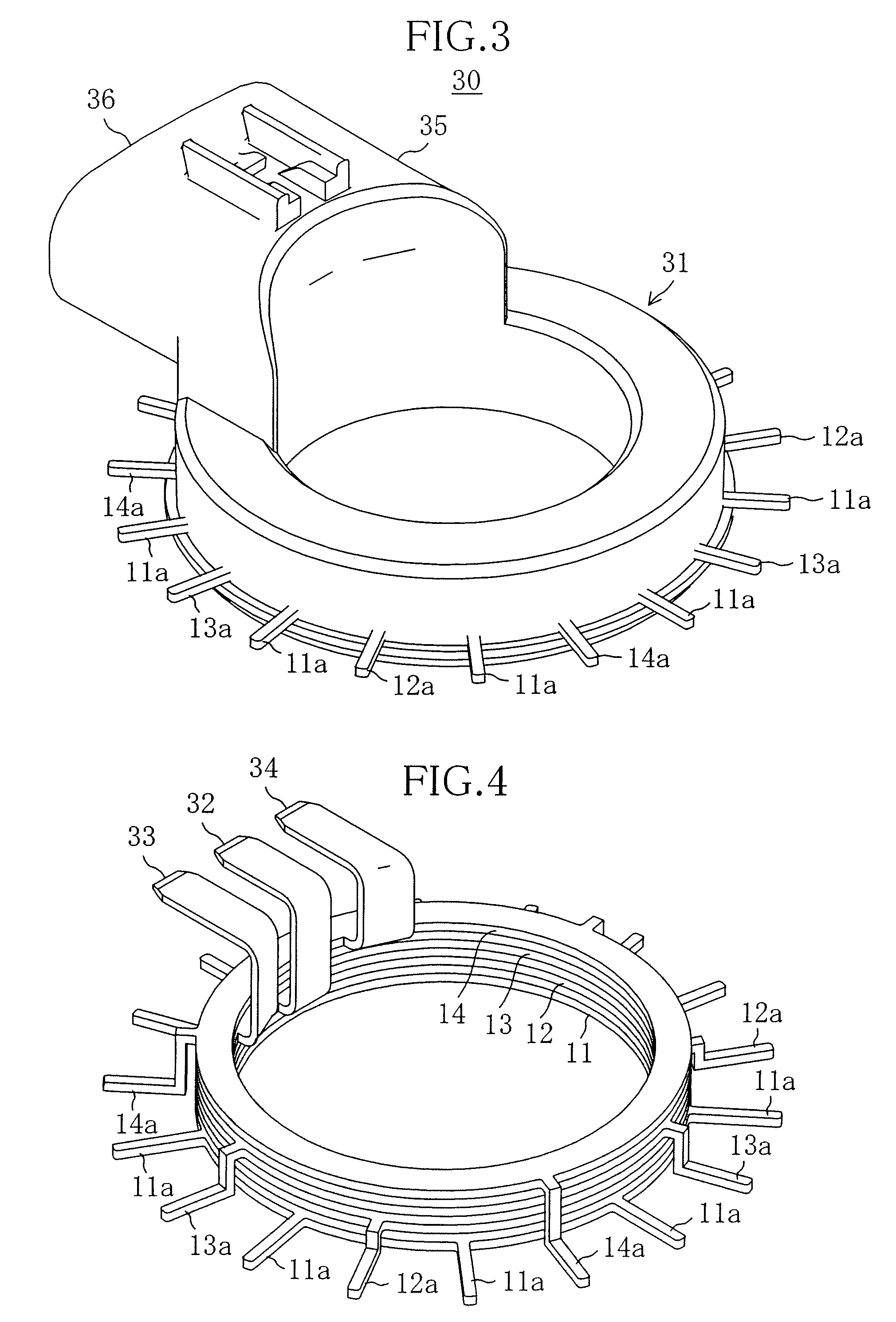
[0044]FIG. 3 is a perspective view illustrating the general structure of an insulating motor housing of a second embodiment and FIG. 4 is a perspective view illustrating the structure of power supply elements of the insulating motor housing.
[0045]The second embodiment is different from the first embodiment in that a connecter insertion hole 36 of the power source connector 35 is opened outward in the radial direction of a motor. The same components as those of the first embodiment are indicated by the same reference numerals and only the difference will be explained below.
[0046]As shown in FIGS. 3 and 4, just like the insulating motor housing 10 of the first embodiment, an insulating motor housing 30 includes first to fourth power supply elements 11 to 14 stacked in a housing body 31 in their thickness direction to be insulated from each other and integrated with the housing body 31 by insert molding.
[0047]The ends of power source terminals 32 to 34 of the second to fourth power sup...
third embodiment
[0051]FIG. 5 is a perspective view illustrating the general structure of an insulating motor housing of a third embodiment, FIG. 6 is a perspective sectional view of the same and FIG. 7 is a perspective view illustrating the structure of the insulating motor housing.
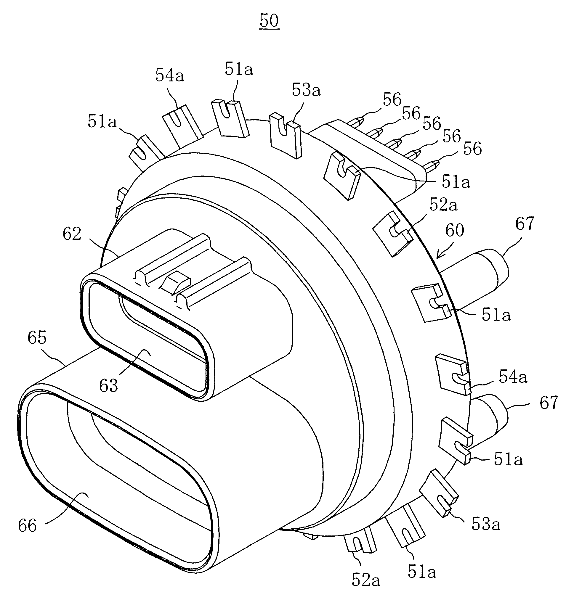
[0052]As shown in FIGS. 5 to 7, an insulating motor housing 50 includes first to fourth power supply elements 51 to 54 which are made of flat conductive metal (e.g., copper) and provided with power source terminals 52b to 54b for connection to a power source and a plurality of coil terminals 51a to 54a for energizing motor coils and a resin housing body 60 for holding the first to power supply elements 51 to 54.
[0053]The first power supply element 51 consists of a ring-shaped element and has a plurality of coil terminals 51a protruding radially outward from its outer rim.
[0054]The second to fourth power supply elements 52 to 54 also consist of ring-shaped elements, respectively, and are sequentially stacked to be spaced ...
PUM
 Abstract
Description
Claims
Application Information