Transmissive-type liquid crystal display device

a liquid crystal display device and transmissive technology, applied in the direction of color television details, instruments, color signal processing circuits, etc., can solve the problems of increasing the power consumption of the backlight, the amount of light absorbed by the color filter is not reducible with the conventional configuration, and the use of the backlight becomes less efficient. , to achieve the effect of reducing power consumption

Inactive Publication Date: 2008-06-26
SHARP KK
View PDF6 Cites 50 Cited by
  • Summary
  • Abstract
  • Description
  • Claims
  • Application Information

AI Technical Summary

Benefits of technology

[0016]An object of the present invention is to provide a transmissive-type liquid crystal display device by which the amount of light absorbed by not only a liquid crystal panel but also a color filter is reduced, whereby the power consumption is reduced further.

Problems solved by technology

Since the liquid crystal panel and the color filter absorb a great amount of light, the use of the light emitted from the backlight becomes less efficient.
Accordingly, a common transmissive-type LCD has the problem of increase in power consumption of the backlight,
However, the amount of light absorbed by the color filter is not reducible with the conventional configuration.

Method used


Image

  • Transmissive-type liquid crystal display device
  • Transmissive-type liquid crystal display device
  • Transmissive-type liquid crystal display device

Examples


Embodiment Construction

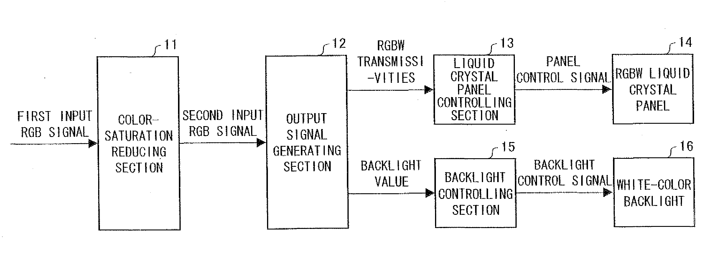
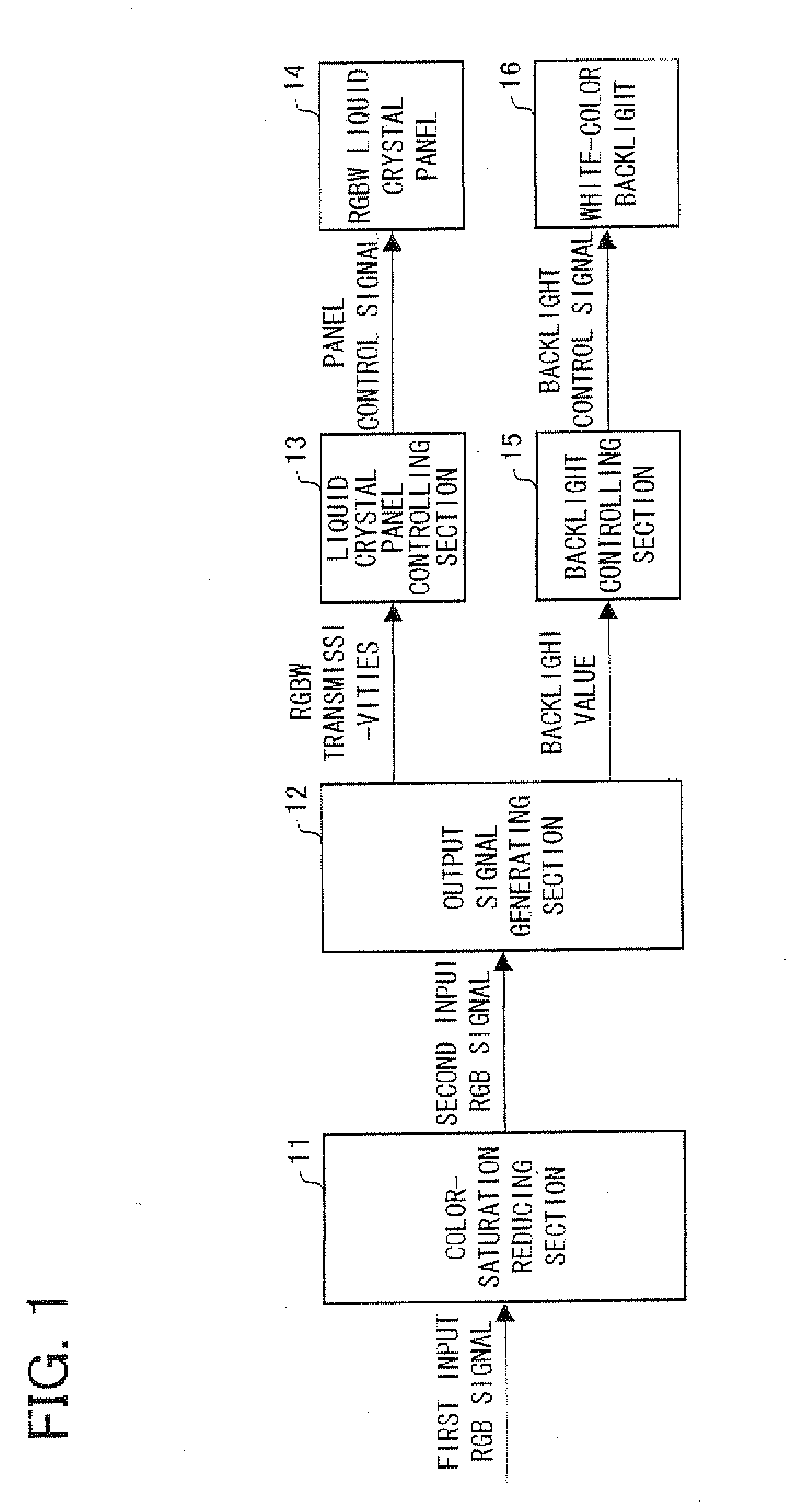
[0040]The following describes an embodiment of the present invention, with reference to the drawings. A schematic configuration of a liquid crystal display device of the present embodiment (the display device will be referred to as a present liquid crystal display device hereinafter) is discussed first in the following description, with reference to FIG. 1.

[0041]The present liquid crystal display device includes a color-saturation reducing section 11, an output signal generating section 12, a liquid crystal panel controlling section 13, an RGBW liquid crystal panel (the panel will be simply referred to as a liquid crystal panel hereinafter) 14, a backlight controlling section 15, and a white-color backlight (the white-color backlight will be simply referred to as a backlight hereinafter) 16.

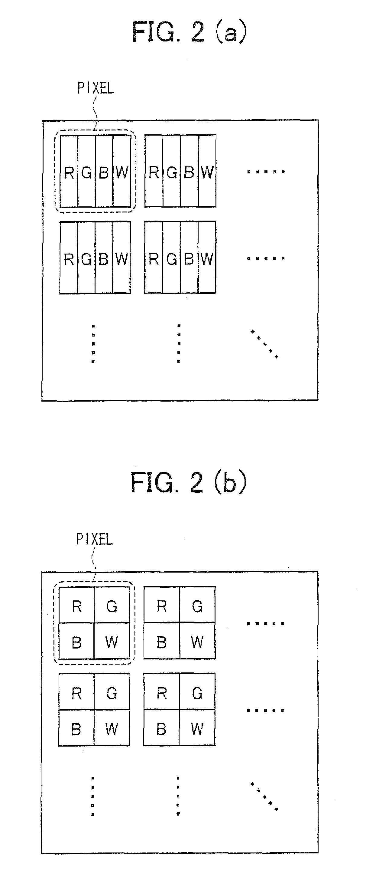
[0042]The liquid crystal panel 14 is constituted of Np pieces of pixels arranged in matrix. As shown in FIGS. 2(a) and 2(b), each pixel is constituted of four sub pixels R (red), G (green), B (bl...


PUM


Abstract

In a transmissive-type liquid crystal display device including a liquid crystal panel and a backlight, the liquid crystal panel has pixels each divided into four subpixels red (R), green (G), blue (B), and white (W). The backlight is a white backlight by which luminance of emitted light is controllable. A color-saturation reducing section carries out a process of reducing color saturation on a first RGB input signal, which is an original input signal, so that the first RGB input signal becomes a second RGB input signal. Thereafter, an output signal generating section obtains a transmissivity and a backlight value on the basis of the second RGB input signal.

Description

[0001]This Nonprovisional application claims priority under 35 U.S.C. § 119(a) on Patent Applications No. 345017 / 2006 filed in Japan on Dec. 21, 2006, and No. 31239 / 2007 filed in Japan on Feb. 9, 2007, the entire contents of which are hereby incorporated by reference.FIELD OF THE INVENTION[0002]The present invention relates to a transmissive-type liquid crystal display device using an active backlight as a light source.BACKGROUND OF THE INVENTION[0003]There are various types of color displays, and they have become practical. Thin displays are roughly classified into self-emitting displays, such as PDP (plasma display panel), and non-luminescent displays exemplified by LCD (liquid crystal display). A known LCD, which is a non-luminescent display, is a transmissive-type LCD having a backlight on a rear side of the liquid crystal panel.[0004]FIG. 13 is a sectional view showing a common configuration of the transmissive-type LCD. The transmissive-type LCD has a backlight 110 on a rear s...

Claims


Application Information

Patent Timeline
Patent Type & Authority Applications(United States)
IPC IPC(8): G09G3/36
CPCG09G3/3406G09G2320/0238G09G2300/0452
Inventor MORISUE, TAKASHIMURAMATSU, TSUYOSHITANAKA, HIROSHIAOKI, ATSUSHI
Owner SHARP KK
Why Eureka
Try Eureka