Retinal scanning image display apparatus and image display system

Inactive Publication Date: 2008-06-26
CANON KK
View PDF6 Cites 68 Cited by
  • Summary
  • Abstract
  • Description
  • Claims
  • Application Information

AI Technical Summary

Benefits of technology

[0012]The present invention provides a small retinal scanning image display apparatus capable

Problems solved by technology

Therefore, there is a problem of in

Method used


Image

  • Retinal scanning image display apparatus and image display system
  • Retinal scanning image display apparatus and image display system
  • Retinal scanning image display apparatus and image display system

Examples


embodiment 1

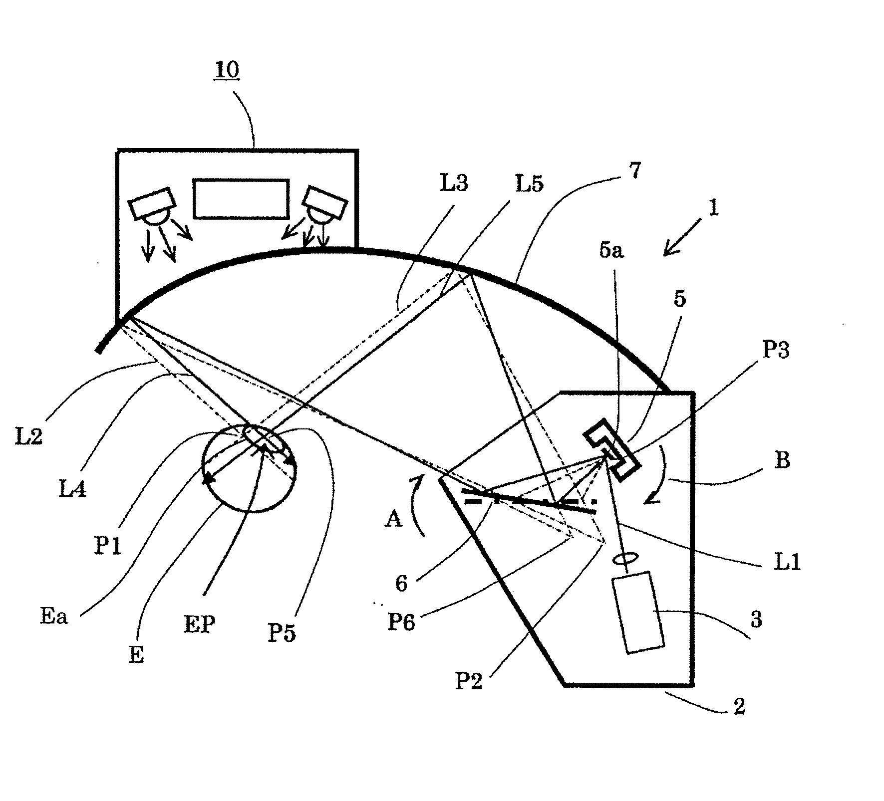
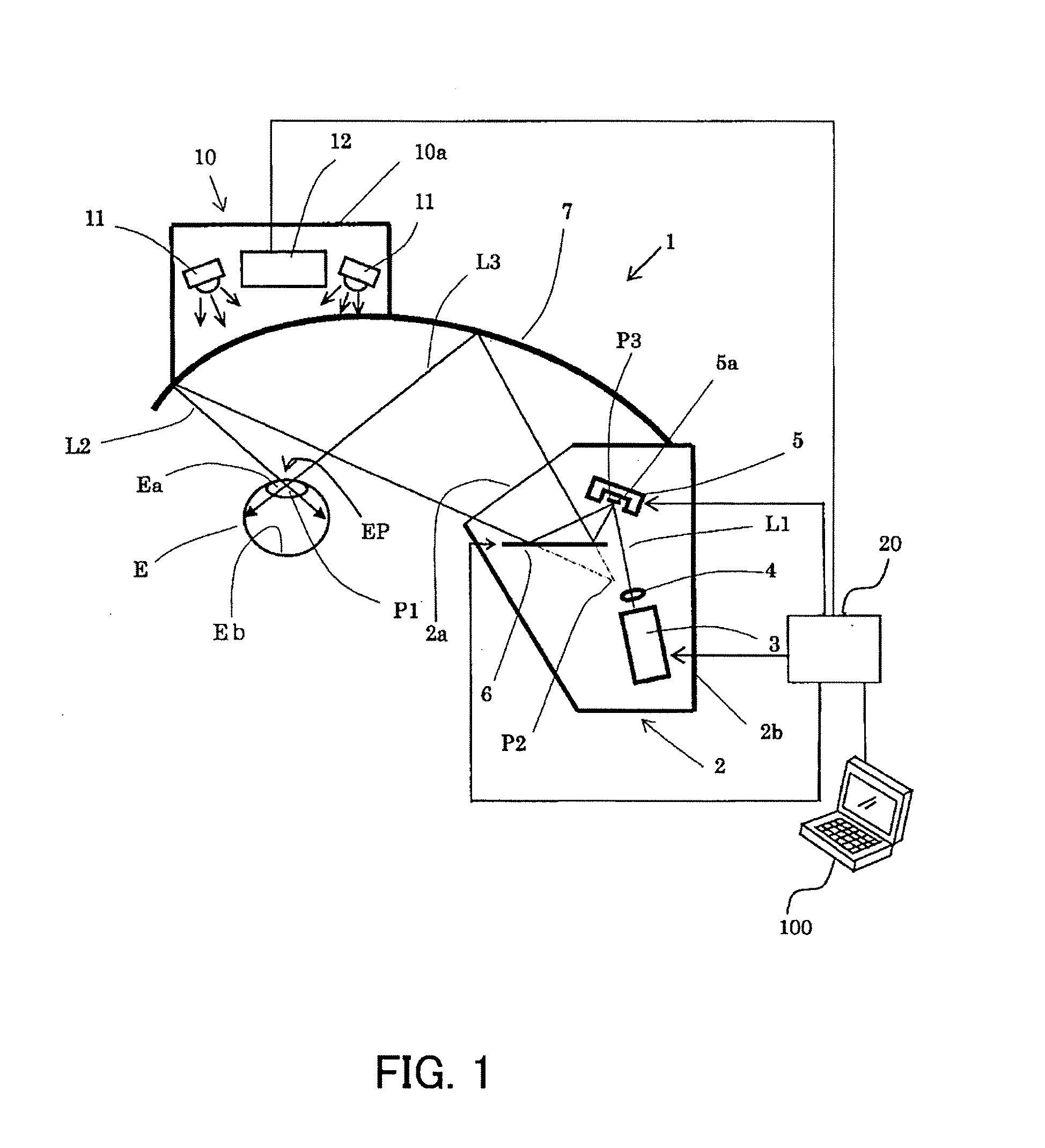
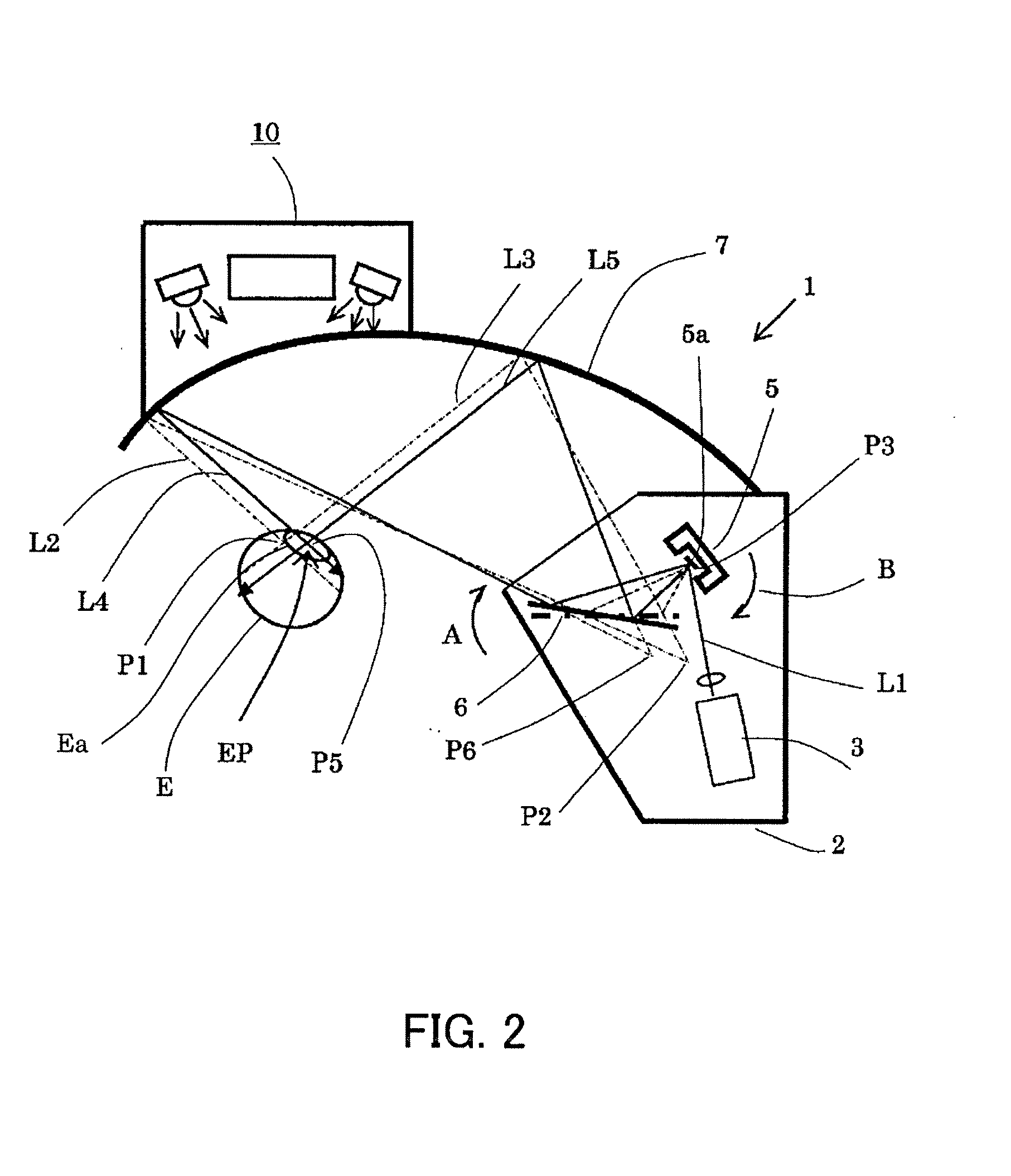
[0027]FIG. 1 shows the configuration of a retinal scanning image display apparatus that is Embodiment 1 of the present invention.

[0028]In FIG. 1, reference numeral 1 denotes an image display apparatus. The image display apparatus 1 includes a scanning part 2 that performs two-dimensional scanning of a light flux modulated in accordance with a video (image) signal from an image supply apparatus 100. The image display apparatus 1 further includes an ocular mirror 7 serving as an ocular unit that causes the optical paths of the light flux scanned by the scanning part 2 to intersect at the position of the exit pupil EP, i.e., that converges the light fluxes there.

[0029]At the position of the exit pupil EP of the ocular mirror 7 or at the vicinity thereof, a pupil Ea of an eye E of an observer is placed. The image display apparatus 1 further includes a pupil detection unit 10 and a controlling part 20, in which the pupil detection unit 10 serves as a detector that detects the motion of t...

embodiment 2

[0058]FIG. 4 shows the configuration of an image display apparatus 1′ that is Embodiment 2 of the present invention.

[0059]In the above-stated Embodiment 1, the scanning unit 5 is rotated so as to keep the incident angle of the light flux to the pupil Ea constant while following the movement of the pupil Ea. On the other hand, in the present embodiment, a first movable planar mirror (a first reflective surface) 13 provided in a scanning part 2′ is shifted instead of the rotation of the scanning unit 5.

[0060]In the present embodiment, the same reference numerals will be assigned to the components common to those of Embodiment 1. The movable planar mirror 6, however, is referred to as a second movable planar mirror (a second reflective surface) 6 in the present embodiment. Although not illustrated, the present embodiment also is provided with a controlling part corresponding to the controlling part 20 described in Embodiment 1.

[0061]In FIG. 4, the light flux L1 from the beam light sour...

embodiment 3

[0067]FIG. 5 shows the configuration of an image display apparatus 1″ that is Embodiment 3 of the present invention. In the above-stated Embodiment 1, the scanning unit 5 is rotated so as to keep the incident angles of the light fluxes to the pupil Ea constant while following the movement of the pupil Ea. On the other hand, in the present embodiment, the drawing timing of the image is controlled instead of rotating the scanning unit 5. More specifically, the light-emitting timing of a beam light source 3 in a scanning part 2′ is controlled.

[0068]In the present embodiment, the same reference numerals will be assigned to the components common to those of Embodiment 1. The optical paths of the scanned light flux guided from the beam light source 3 to the eye E of the observer are the same as those in Embodiment 1. Although not illustrated, the present embodiment also is provided with a controlling part corresponding to the controlling part 20 described in Embodiment 1.

[0069]In the pres...


PUM


Abstract

A retinal scanning image display apparatus includes a light source, a scanning unit that scans a light flux from the light source, a reflective surface that reflects the light flux from the scanning unit, and an ocular unit that guides the light flux from the reflective surface to an eye of an observer. Optical paths of the light flux scanned by the scanning unit intersect at an exit pupil position of the ocular unit, and the image display apparatus causes the scanning unit and the reflective surface to shift so that the optical paths of the scanned light flux toward the same image position are respectively moved in parallel to move the intersecting position of those optical paths. This realizes a small retinal scanning image display apparatus capable of keeping the image position substantially constant even when an observer moves their pupil.

Description

BACKGROUND OF THE INVENTION[0001]The present invention relates to a retinal scanning image display apparatus that draws an image on a retina of an observer by guiding a light flux modulated in accordance with a video (image) signal to a pupil of the observer and scanning the light flux two-dimensionally.[0002]In an image display apparatus as stated above, an image is drawn directly on the retina through the pupil of the observer by scanning laser light two-dimensionally. Among this sort of apparatuses, there is an apparatus adapted to detect the motion of the pupil of the observer and causes laser light to enter the pupil so as to follow the motion, thus avoiding the image from disappearing even when the observer moves their pupils (see Japanese Patent Laid-Open No. 7 (1995)-135623).[0003]As shown in FIG. 6A, however, when the pupil Ea of the observer shifts (rotates) from position P10 to position P11, the converging point P10 of the image light flux La1, Lb1, and Lc1 needs to be sh...

Claims


Application Information

Patent Timeline
IPC IPC(8): A61B3/14
CPCA61B3/113A61B3/12G02B2027/0187G02B27/0101G02B26/10
Inventor SAITO, YOSHIHIROYAMAMOTO, AKIRATSUYUKI, TAKASHI
Owner CANON KK
Why Eureka
Try Eureka