Disk drive device and carriage of actuator used therein

Inactive Publication Date: 2008-06-26
WESTERN DIGITAL TECH INC
View PDF18 Cites 4 Cited by
  • Summary
  • Abstract
  • Description
  • Claims
  • Application Information

AI Technical Summary

Benefits of technology

[0014]Embodiments in accordance with the present invention suppress performance degradation in an actuator of a disk drive device when attaching a damping member to a single surface of an arm. According to the particular embodiment of FIG. 3, in a HDD 1, a damping member 108 is attached to a single surface of an arm 111. Besides, a shape of an inner arm 111b is asymmetric with the center position between

Problems solved by technology

With finer track pitch for high-capacity and high recording density and speed-up of driving, required conditions for vibration of the HSA has become severer.
Adhering the

Method used


Image

  • Disk drive device and carriage of actuator used therein
  • Disk drive device and carriage of actuator used therein
  • Disk drive device and carriage of actuator used therein

Examples


Example

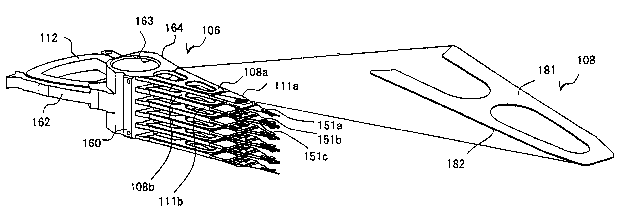
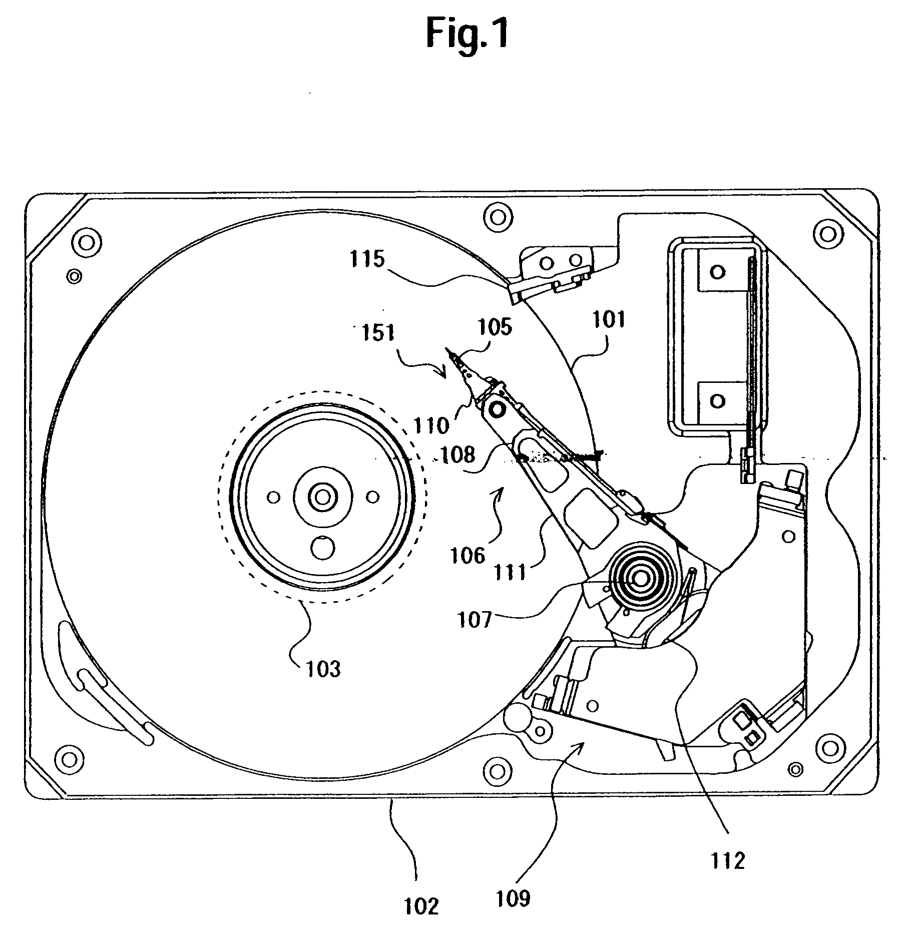
[0025]Embodiments of the present invention relate to a disk drive device and a carriage of an actuator used therein, in particular to an arm structure of the carriage to which a damping member is attached.

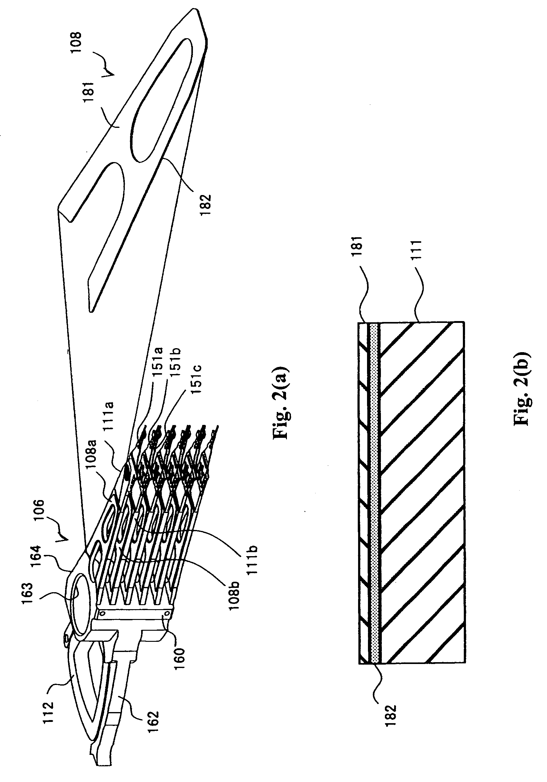
[0026]An aspect of embodiments of the present invention is a carriage including an arm to which head supporting members is attached and pivoting in a disk drive device. In this carriage, the arm includes two head supporting member attaching surfaces to each of which the head supporting member is attached, a damping member attaching surface which is on the same side as one of the two head supporting member attaching surfaces and is covered by a damping member, and an opposite surface which is an opposite surface to the damping member attaching surface and is exposed. A thickness from a center position between the two head supporting member attaching surfaces to the damping member attaching surface is thinner than a thickness from the center position to the opposite surface. This str...


PUM


Abstract

Embodiments of the present invention help to suppress performance degradation in an actuator of a disk drive device when attaching a damping member to a single surface of an arm. According to one embodiment, in a HDD a damping member is attached to a single surface of an arm. A shape of an inner arm is asymmetric with the center position between disks. Specifically, the thickness from a center position between the disks to the damping material attaching surface is thinner than the thickness from a center position between the disks to an opposite surface of the damping member attaching surface. This suppresses deformation of the vibration mode in the case that the damping member is attached to the single surface of the arm.

Description

CROSS-REFERENCE TO RELATED APPLICATION[0001]The instant nonprovisional patent application claims priority to Japanese Patent Application No. 2006-348673 filed Dec. 25, 2006 and which is incorporated by reference in its entirety herein for all purposes.BACKGROUND OF THE INVENTION[0002]A hard disk drive (hereinafter referred to as HDD) in recent years rotates a magnetic disk and drives a head stack assembly (hereinafter referred to as HSA) at high speed in response to the request for high capacity and high recording density, additionally high-speed accessing. As schematically illustrated in a side view of FIG. 8(a), the HSA includes a carriage 160 and head gimbal assemblies (hereinafter referred to as HGAs) 151 and pivots around a pivotal axis.[0003]The HGA 151 is an assembly of a suspension and a head slider. Typically, the HSA has a plurality of arms 111. In FIG. 8, a top end arm 111a and one of the inner arms 111b are exemplarily designated with reference numerals. An inner arm is ...

Claims


Application Information

Patent Timeline
IPC IPC(8): G11B5/54G11B21/22
CPCG11B5/4833
Inventor SOGA, EIJISASAKI, MASAKAZUEGUCHI, HAJIMEMASUDA, HIROMITSU
Owner WESTERN DIGITAL TECH INC
Why Eureka
Try Eureka