
Computer case with intake filter with positive airflow

Inactive Publication Date: 2008-06-26
MADDOX CHARLES W
View PDF60 Cites 36 Cited by
  • Summary
  • Abstract
  • Description
  • Claims
  • Application Information

AI Technical Summary

Benefits of technology

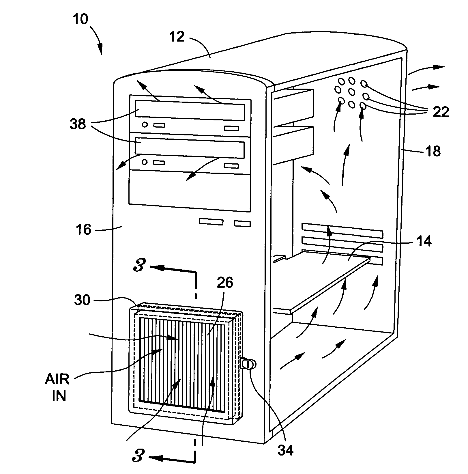
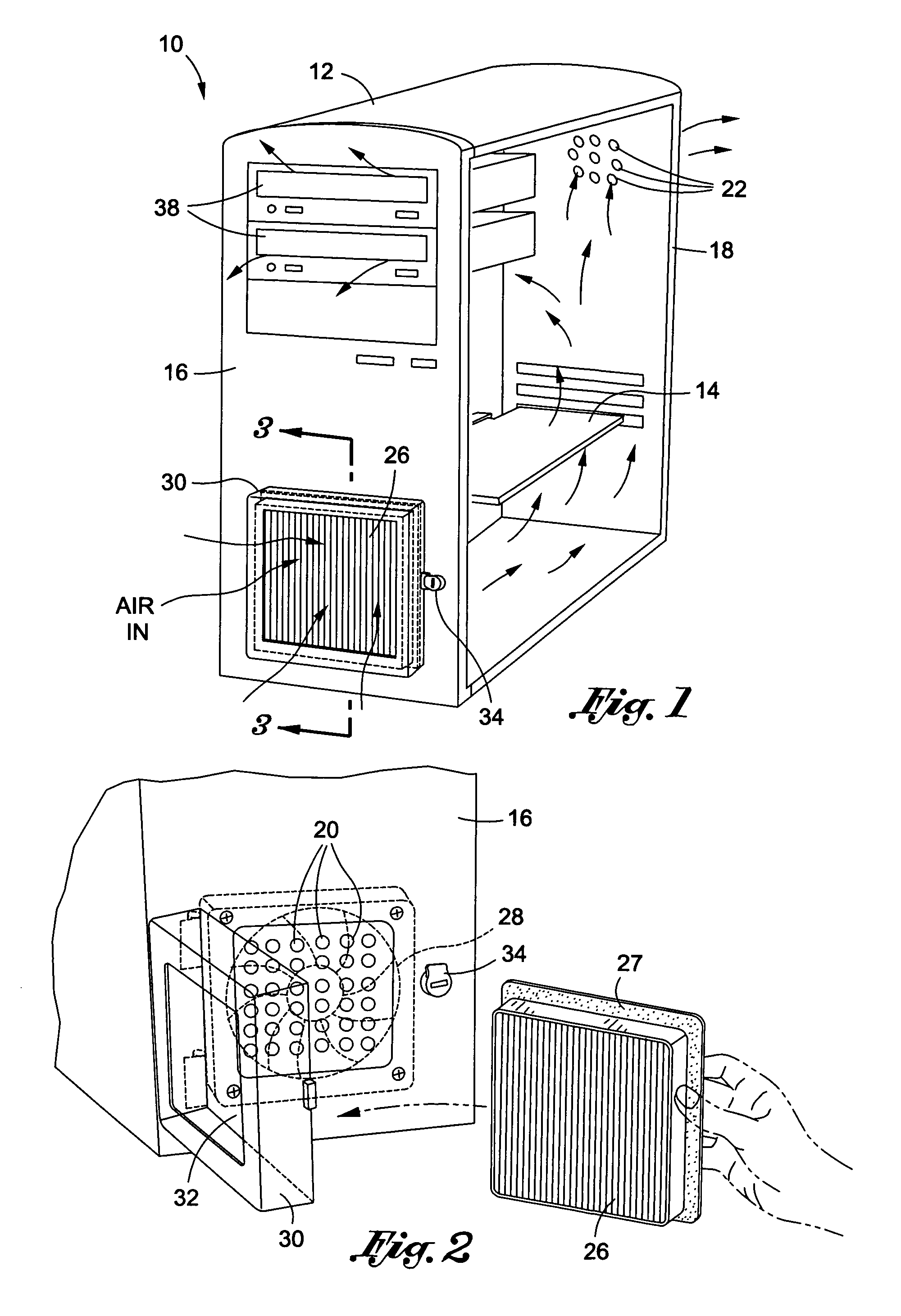
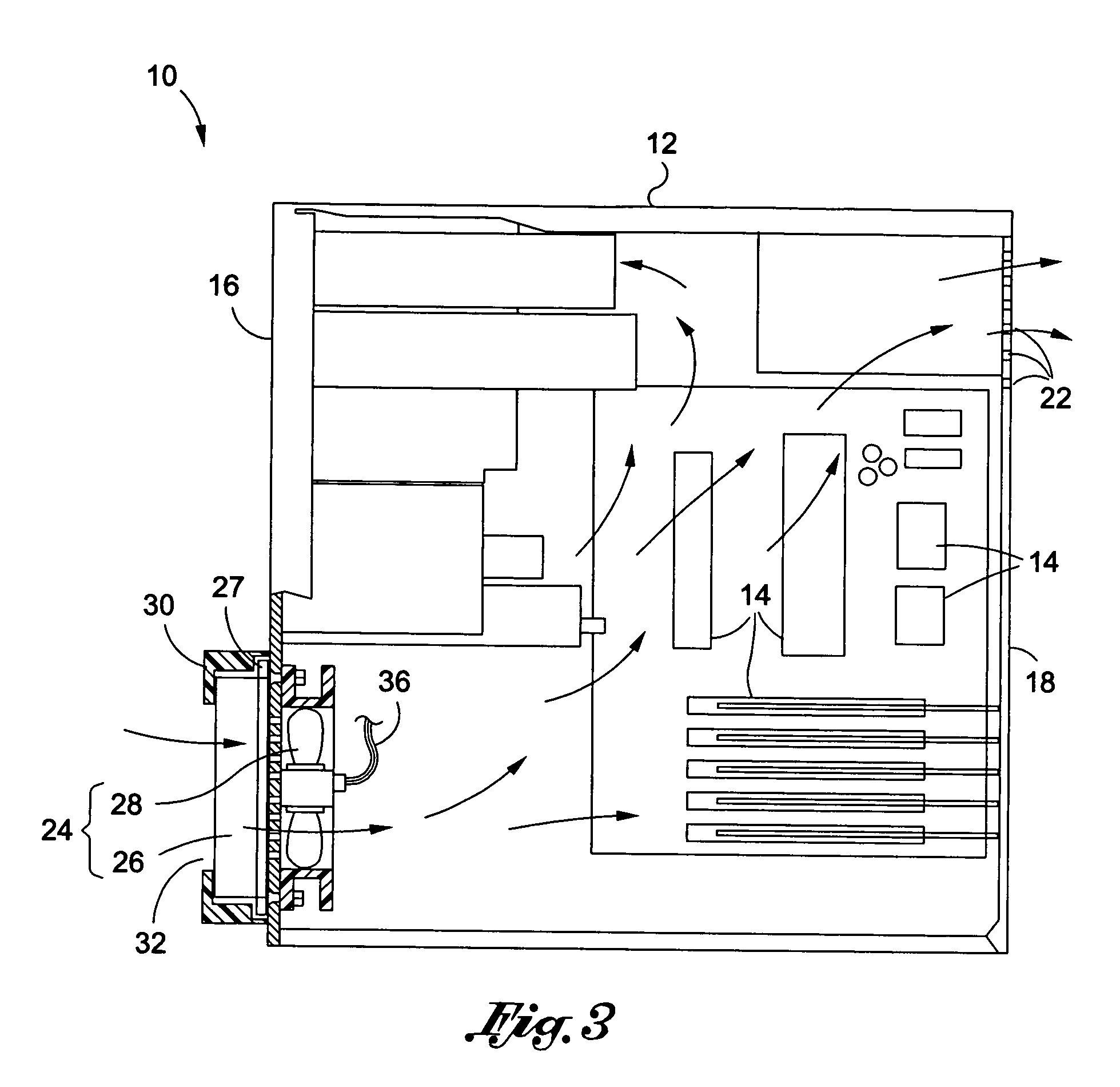
[0014]It is contemplated that the computer case mitigates the introduction of airborne particles into the enclosure by creating a positive air pressure within the enclosure. The positive air pressure is a result of the second flow rate being greater than the first flow rate. In other words, more air is being introduced into the enclosure through the inlet opening than is leaving the enclosure through the outlet opening. Furthermore, air directed into the enclosure passes through a filter, thereby purifying the air. The computer case may also create airflow flowing from the forward face to the rearward face, which is similar to airflow within a typical computer case. Consequently, air flows over the computer components in a manner similar to many existing computer cases.
[0017]It is contemplated that the modular computer airflow generator is positionable in fluid communication with the inlet assembly of an existing computer case to inhibit the introduction of airborne particles into the case. In this regard, the modular computer airflow generator may be used in connection with various computer cases. Therefore, if an existing computer case does not have sufficient airflow and filtering systems, the modular computer airflow generator may be employed to facilitate the airflow and to mitigate the introduction of airborne particles into the enclosure.

Problems solved by technology

Computers include many delicate components which may only operate within a specific temperature range.
If the temperature of a particular component exceeds its maximum operating temperature, the component may become damaged.
In either case, computer operation is likely interrupted, which may result in the loss of data and downtime to the user.
However, the ambient air drawn into the computer case includes dust and foreign particles which may mitigate the cooling of the computer components.
Although component damage caused by dust and foreign particles may occur anywhere, such damage may be particularly prevalent in environments with high concentrations of dust and foreign particles.
Therefore, access to the computer is restricted.

Method used


Image

  • Computer case with intake filter with positive airflow
  • Computer case with intake filter with positive airflow
  • Computer case with intake filter with positive airflow

Examples


Embodiment Construction

[0024]It is well known that computer components generate heat as they operate. Each component is generally operable within a specific temperature range. Therefore, most prior art computer cases include a cooling system aimed at maintaining the temperature of the components within their operable temperature range. Many cooling systems create airflow flowing directly over the computer components. Cool ambient air is drawn into the computer while hot air is blown out of the computer. As the cool air flows over the components, heat from the components is transferred to the passing air. In general, air flows in one side, and out an opposing side. As such, the airflow in most computer cases typically flows from an inlet vent disposed on a front panel of the computer case to an outlet vent disposed on the back panel. The outlet vent is typically positioned on the back panel to prevent warm air from blowing onto the person operating the computer. An exhaust fan is normally positioned adjace...


PUM


Abstract

There is provided a computer case including an enclosure having a forward face and a rearward face. An inlet opening is formed on the forward face and is configured to allow ambient air to enter the enclosure through the inlet opening. At least one outlet opening is formed on the rearward face and is configured to allow air within the enclosure to exit through the outlet opening at a first flow rate. The inlet opening and the outlet opening are in fluid communication with each other to define airflow from the forward face to the rearward face within the enclosure. The computer case further includes an inlet assembly in fluid communication with the inlet opening. The inlet assembly includes an air filter and a fan. The fan directs air through the filter and into the inlet opening at a second flow rate being greater than the first flow rate.

Description

CROSS-REFERENCE TO RELATED APPLICATIONS[0001]The present application claims priority to Provisional Application No. 60871934 filed on Dec. 26, 2006 entitled Filtered, Pressurized Computer Case for Personal Computers and Servers, the entire contents of which are incorporated herein by reference.STATEMENT RE: FEDERALLY SPONSORED RESEARCH / DEVELOPMENT[0002](Not Applicable)BACKGROUND OF THE INVENTION[0003]1. Field of the Invention[0004]The present invention relates generally to computer component protection and more particularly, to a computer case having a positive air pressure to substantially inhibit the introduction of foreign particles into the case and to create an airflow that facilitates cooling of computer components.[0005]2. Description of the Related Art[0006]Computers include many delicate components which may only operate within a specific temperature range. If the temperature of a particular component exceeds its maximum operating temperature, the component may become damag...

Claims


Application Information

Patent Timeline
IPC IPC(8): H05K7/20
CPCG06F1/20
Inventor MADDOX, CHARLES W.
Owner MADDOX CHARLES W
Learn More