Crop raking device

a raking device and crop technology, applied in the field of crop raking devices, can solve the problems of serious devaluation of the end product on which the producer depends, affecting the quality of crop products, so as to reduce the introduction of contaminants into forag

Active Publication Date: 2008-04-01
STAHELI DAVID H
View PDF21 Cites 6 Cited by
  • Summary
  • Abstract
  • Description
  • Claims
  • Application Information

AI Technical Summary

Benefits of technology

[0014]It has been recognized that it would be advantageous to develop a rake wheel system that more consistently reduces the introduction of contaminants into forage.
[0015]It has also been recognized that it would be advantageous to develop a wheel rake system that maintains the height of a rake wheel above the ground in a variety of conditions, and which is simple in design It has also been recognized that it would be advantageous to develop a wheel rake height maintenance system that can be easily retrofitted onto existing wheel rakes.

Problems solved by technology

Each component of the harvest procedure presents challenges, and each, if handled improperly, poses the risk of seriously devaluing the end product on which the producer depends.
Rocks, dirt clods, soil particles, and other debris and contaminants in hay and forage products significantly reduce sales or seriously reduce the price producers can obtain for their product.
These contaminants can be introduced into forages during various operations of the harvest.
However raking is where most forage contamination occurs.
When rake teeth or other portions of a raking device dig into the soil, rather than staying above it, they introduce these contaminants into the forage.
However, basket rakes are generally considered to be too slow in the commercial hay industry.
The current design of wheel rakes requires a delicate balance between trying to effectively gather cut hay swaths or windrows (without leaving valuable crop in the field), while trying to keep the rake teeth out of the soil.
It is difficult to maintain optimum raking accuracy because large modern wheel rakes cover swaths as wide as 40 feet or more, with operating lengths up to 30 feet.
At any given time, within the length and breadth of such an operating area, there can be large enough variations in the field elevation to cause either undesirable contact between the rake teeth and the soil surface, or excessive rake tooth operating height in other locations.
There have not been many significant technological advancements in hay and forage raking for many years.
Indeed, until recently, market forces have not particularly focused on the problem of contaminated forage, and players in the market have not complained too loudly about this problem.
However, this appears to be changing due to a variety of market forces.
Export markets are becoming particularly sensitive to contamination of forages with soil or other soil-borne products because of the perceived risk of biological contamination of their native soils with soil-borne organisms from other countries.
Additionally, equipment maintenance is also affected by poor raking performance.
Rake teeth are very expensive, and wear out quickly when they frequently contact a soil surface.
Furthermore, machinery used in other operations, such as machinery for subsequent harvest operations, bearings, cutting knives, pellet and hay cube dies etc., also wears at an accelerated rate when abrasive soil or aggregate substances are present in the forages they process.
Unfortunately, this scuffing action is sufficient to dislodge small rocks, gravel, small soil clods, soil particles and other debris, and to propel a portion of these into the forage being raked.
Additionally, if an operator does not adjust the wheel rake regularly, the contact between the rake teeth and the soil can become excessive causing excessive wear and / or breakage of the rake teeth and excessive contamination of the forage being raked.
Thousands of tons of forage can be contaminated relatively quickly with poor rake performance.
However, significant contamination problems still exist in soft soils and sandy soil because the depth bands themselves, being relatively narrow (e.g. about 1 inch wide) can fairly easily penetrate these soil types, allowing both the depth band and the rake teeth to throw soil particles into the forage being raked.

Method used


Image

  • Crop raking device
  • Crop raking device
  • Crop raking device

Examples


Embodiment Construction

[0028]Reference will now be made to the exemplary embodiments illustrated in the drawings, and specific language will be used herein to describe the same. It will nevertheless be understood that no limitation of the scope of the invention is thereby intended. Alterations and further modifications of the inventive features illustrated herein, and additional applications of the principles of the inventions as illustrated herein, which would occur to one skilled in the relevant art and having possession of this disclosure, are to be considered within the scope of the invention.

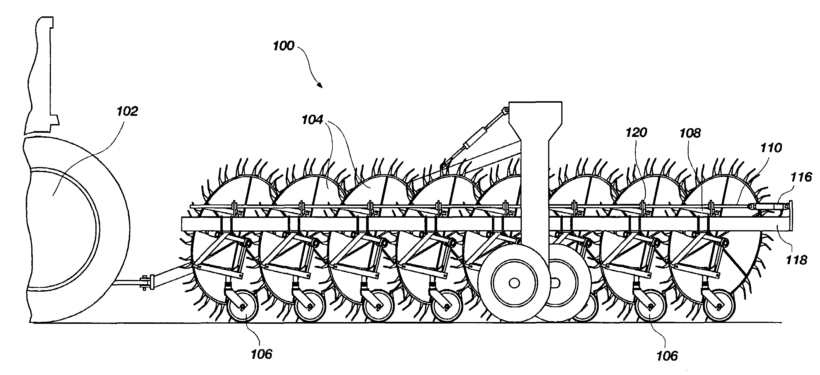
[0029]The present invention reduces or eliminates the common problem of hay and forage contamination caused by modern wheel rakes. It also helps reduce rake tooth wear and wear to other components of the rake and other machinery used “downstream” in the hay and forage processing and consumption industry. It also increases forage quality and palatability. The disclosed method and devices herein described combine c...


PUM


Abstract

A crop raking device includes a rake wheel and a gauge wheel. The rake wheel is configured to rake crop in a field, with teeth disposed around a perimeter thereof, and has a vertically variable position. The gauge wheel is attached to the rake wheel, and is configured to contact ground behind the rake wheel and maintain a height of the rake wheel teeth with respect to the ground. The gauge wheel is configured to maintain a substantially constant upright orientation regardless of the vertical position of the rake wheel.

Description

BACKGROUND OF THE INVENTION[0001]1. Field of the Invention[0002]The present invention relates generally to agricultural equipment. More particularly, the present invention relates to a crop raking device that maintains a more consistent position with respect to the ground.[0003]2. Related Art[0004]In typical hay and forage operations, harvest practices become the determining factor as to whether a valuable crop standing in the field will still be valuable when it is in the barn, in the stack, in the silage bag, pit or silo, or in the manger where it is used as feed. Each component of the harvest procedure presents challenges, and each, if handled improperly, poses the risk of seriously devaluing the end product on which the producer depends.[0005]In silage operations various forages are cut green into windrows. Two or more windrows are raked together to create a larger windrow which will satisfy the appetite of modern high capacity forage harvesters. In nearly all dry hay and forage...

Claims


Application Information

Patent Timeline
Patent Type & Authority Patents(United States)
IPC IPC(8): A01D84/00
CPCA01D78/142
Inventor STAHELI, DAVID H.
Owner STAHELI DAVID H
Why Eureka
Try Eureka