Furnaces having dual gas screens and methods for operating the same

a gas screen and dual technology, applied in the field of furnaces, can solve the problems of inability to provide a sufficiently high flow rate and insufficient seals, and achieve the effect of reducing the introduction of contaminant gases

Inactive Publication Date: 2005-02-24
BIRD LINDWOOD A +3
View PDF7 Cites 6 Cited by
  • Summary
  • Abstract
  • Description
  • Claims
  • Application Information

AI Technical Summary

Benefits of technology

[0009] In further embodiments of the present invention, draw furnace assemblies for manufacturing optical fiber are provided including a draw furnace defining an internal draw chamber extending therethrough. A first gas screen is positioned adjacent a downstream end of the draw furnace. The first gas screen is configured to introduce a process gas into the internal draw chamber at the downstream end of the draw furnace. A second gas screen is positioned adjacent to the first gas screen at an opposite end of the first gas screen from the draw furnace. The second gas screen is configured to introduce a sealing gas to provide a seal for the downstream end of the draw furnace. The sealing gas may be a heavier gas than the process gas. A flow controller is provided that controls a flow rate of the process gas from the first gas screen and a flow rate of the sealing gas from the second gas screen to provide a desired flow rate of the process gas from the downstream end to an upstream end of the draw furnace and to provide a desired flow rate of the sealing gas from the second gas screen downstream from the downstream end of the draw furnace so as to reduce introduction of contaminant gases into the internal draw chamber while a preform positioned in the internal draw chamber is heat

Problems solved by technology
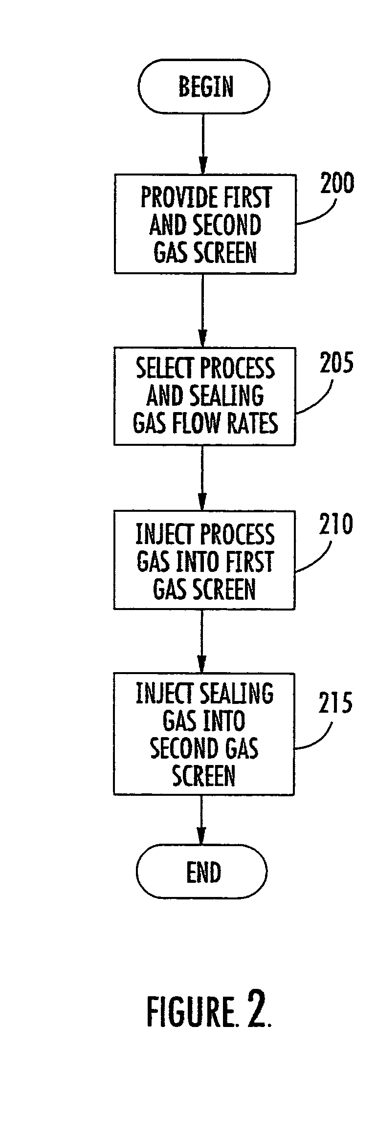
Such an approach may create difficulties when used in a process using upward gas flow of process gases during drawing of an optical fiber.
More particularly, while a gas screen in such a system may be provided with sufficient flow of process gas to cause such gas to flow both upward through the treatment area as well as downwards to contribute toward

Method used


Image

  • Furnaces having dual gas screens and methods for operating the same
  • Furnaces having dual gas screens and methods for operating the same
  • Furnaces having dual gas screens and methods for operating the same

Examples


Embodiment Construction

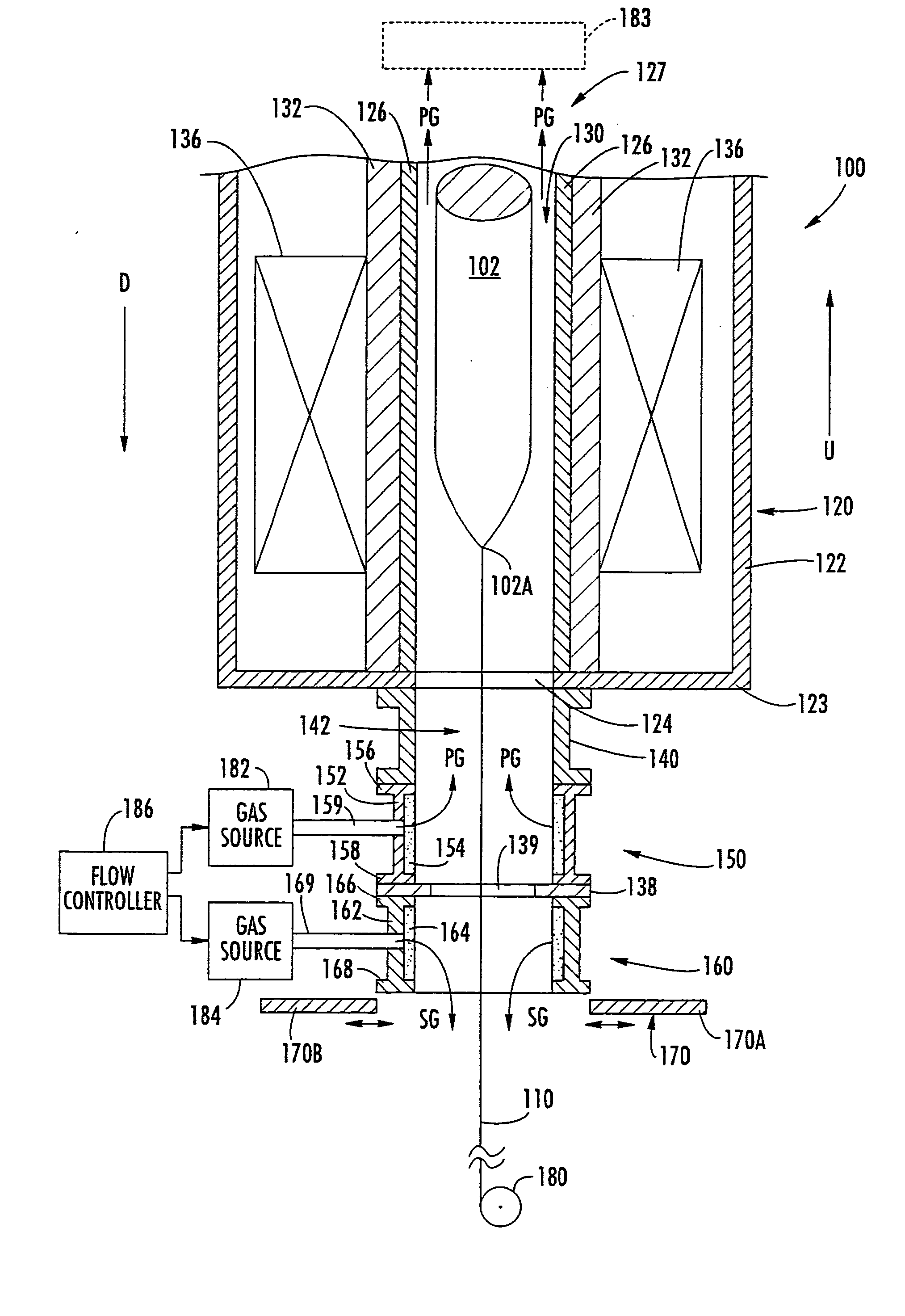
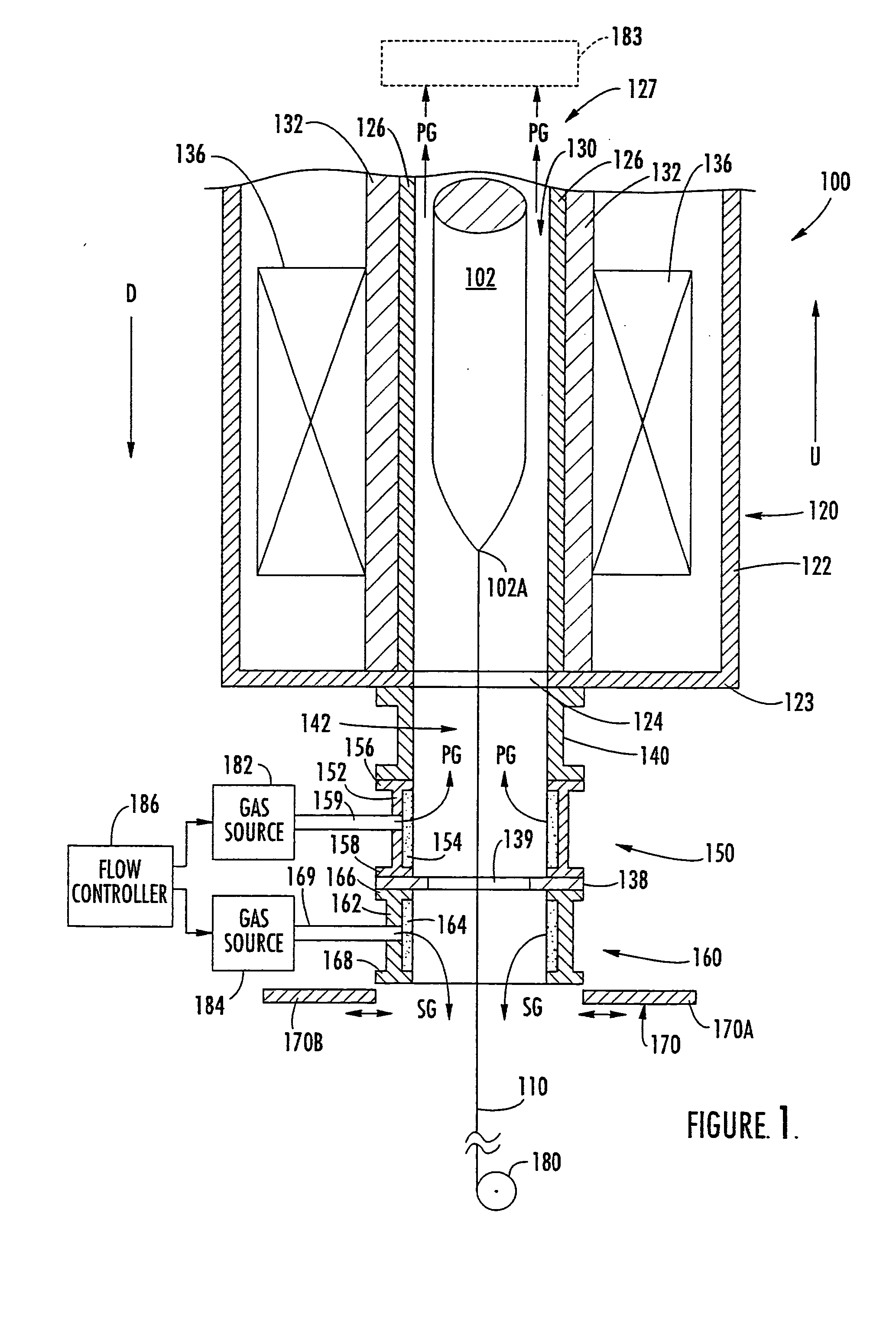
[0013] The present invention now will be described more fully hereinafter with reference to the accompanying drawings, in which preferred embodiments of the invention are shown. This invention may, however, be embodied in many different forms and should not be construed as limited to the embodiments set forth herein; rather, these embodiments are provided so that this disclosure will be thorough and complete, and will fully convey the scope of the invention to those skilled in the art. In the drawings, the thickness of members, layers and regions are exaggerated for clarity. Like numbers refer to like elements throughout. It will be understood that when an element such as a member layer, region or substrate is referred to as being “on,”“connected to” or “coupled to” another element, it can be directly on, directly connected to or directly coupled to the other element, or intervening elements also may be present. In contrast, when an element is referred to as being “directly on,”“dir...


PUM

PropertyMeasurementUnit
Fractionaaaaaaaaaa
Fractionaaaaaaaaaa
Concentrationaaaaaaaaaa

Abstract

Furnace assemblies are provided including a furnace defining an internal process chamber extending therethrough. A first gas screen is coupled to the furnace. The first gas screen is configured to introduce a first gas into the internal process chamber at a first end of the furnace. A second gas screen is positioned adjacent to the first gas screen at an opposite end of the first gas screen from the furnace. The second gas screen is configured to introduce a second gas to provide a seal for the first end of the furnace. The furnace may be a draw furnace and the process chamber may be an internal draw chamber.

Description

FIELD OF THE INVENTION [0001] This invention relates to furnaces, and, more particularly, furnaces for manufacturing optical fibers and methods for using the same. BACKGROUND OF THE INVENTION [0002] With the expansion of telecommunications services, there has been a great demand for optical fibers. Optical fibers are typically formed by drawing while heating and melting a transparent optical fiber preform in an optical fiber drawing furnace. Such furnaces typically draw the optical fiber while maintaining a flow of process gas around the optical fiber during processing. Such fiber drawing furnaces further conventionally flow the process gases from an end of the furnace adjacent the preform through to an opposite end of the draw furnace, which direction will generally be referred to herein as a downward flow. Examples of such a draw furnace are described, for example, in U.S. Pat. Nos. 5,848,093 and 5,637,130. It is also known, however, to use an upward flow of process gas in a draw ...

Claims


Application Information

Patent Timeline
IPC IPC(8): C03B37/029
CPCC03B37/029C03B2205/98C03B2205/91C03B2205/83
Inventor BIRD, LINDWOOD A.JEWELL, JOHN M.SURRATT, DAVID G. JR.WU, ZHENMING
Owner BIRD LINDWOOD A
Why Eureka
Try Eureka