Method of monitoring microseismic events

Inactive Publication Date: 2008-06-26
SCHLUMBERGER TECH CORP
View PDF2 Cites 27 Cited by
  • Summary
  • Abstract
  • Description
  • Claims
  • Application Information

AI Technical Summary

Benefits of technology

[0023]The S-wave velocity in the vicinity of a receiver is usually a well-known or at least readily accessible measurement.

Problems solved by technology

Apart from the problem of detecting the often faint microseismic events, their interpretation is difficult as neither the source location nor the source signature or characteristics are known a priori.
However, the hydraulic fracturing process is difficult to monitor and control.
The hydraulic fractures cannot be readily observed, since they are typic

Method used


Image

  • Method of monitoring microseismic events
  • Method of monitoring microseismic events
  • Method of monitoring microseismic events

Examples


Embodiment Construction

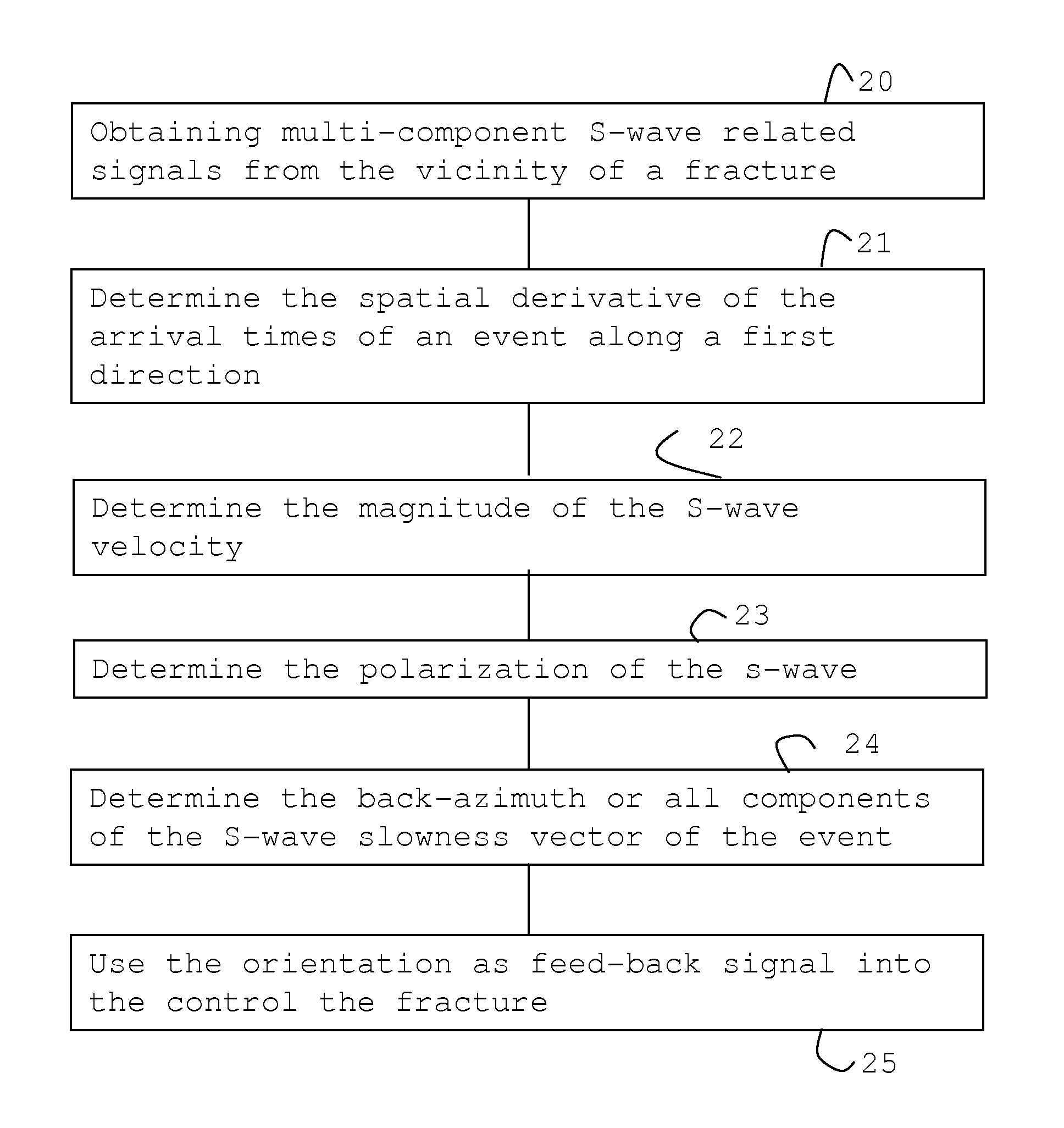
[0033]A typical operational setting for monitoring hydraulic fracturing is illustrated in FIG. 1 with a treatment well 11 and geophone arrays 121, 131 located in neighboring wells or holes 12, 13. During the fracturing operation a fluid is pumped from the surface 10 into the treatment well 11 causing the surrounding formation in a hydrocarbon bearing layer 101 to fracture. S-waves 14 generated by the fracture 111 propagate through the earth and are recorded by the three-components geophones of the two arrays 121, 131 in the monitoring wells 12, 13.

[0034]For the present invention it is assumed that three components of the time history of particle velocity (or particle displacement or acceleration) at several downhole or surface receivers are recorded for an acoustic emission and include at least the S-wave arrivals at all of those receivers.

[0035]The slowness vector {right arrow over (p)} of the detected S-wave is determined from the S-wave arrival-times TS(z), where z is a coordinat...


PUM


Abstract

A microseismic method of monitoring fracturing operation or other passive seismic events in hydrocarbon wells is described using the steps of obtaining multi-component s-wave signals of the event; and using a linear derivative of S-wave arrival times of the signals in a first direction, an S-wave velocity and an s-wave polarization to determine at least two components of the S-wave slowness vector.

Description

[0001]This invention relates to methods for acquiring seismic data, particularly passively monitoring seismic events. Such monitoring may be applied to hydrocarbon reservoirs, subterranean water-bearing layers or storage sites for carbon dioxide and waste. It also relates to monitoring hydraulic stimulation such as fracturing rock layers with subterranean locations. More specifically it relates to such methods using seismic methods to determine the location of microseismic events or operations.BACKGROUND OF THE INVENTION[0002]Seismic monitoring is known as a method with an observation horizon that penetrates far deeper into a hydrocarbon reservoir than any other method employed in the oilfield industry. It has been proposed to exploit the reach of seismic methods for the purpose of reservoir monitoring.[0003]In conventional seismic monitoring a seismic source, such as airguns, vibrators or explosives are activated and generate sufficient acoustic energy to penetrate the earth. Refle...

Claims


Application Information

Patent Timeline
IPC IPC(8): G01V1/30
CPCG01V1/30G01V1/008
Inventor EISNER, LEOFISCHER, TOMAS
Owner SCHLUMBERGER TECH CORP
Why Eureka
Try Eureka