Ultra-wideband antenna array

a multi-element antenna array and ultra-wideband technology, applied in the field of ultra-wideband communication systems, can solve the problems of reducing the signal strength of the uwb, adding to the electromagnetic noise surrounding, and difficult to realize the ideal environment outside the vacuum of outer space, so as to increase the signal-to-noise ratio of received uwb pulses

Inactive Publication Date: 2006-05-09
INTELLECTUAL VENTURES HLDG 73
View PDF22 Cites 115 Cited by
  • Summary
  • Abstract
  • Description
  • Claims
  • Application Information

AI Technical Summary

Benefits of technology

[0006]In order to increase the signal-to-noise ratio, and overcome multipath interference, an ultra-wideband (UWB) antenna array is provided. Briefly, one embodiment of the present invention employs a multi-element antenna for UWB beam forming and also for time-of-arrival vector processing to resolve multi-path problems in an UWB communication system. Another embodiment of the present invention recovers the energy contained in the multi-path reflections to increase signal-to-noise ratios of received UWB pulses.

Problems solved by technology

Such an ideal environment is difficult to realize outside the vacuum of outer space.
Indeed, via such multiple paths, or multipaths, portions of the UWB signal can arrive at a receiver at different times. In this situation, the UWB signal strength is diminished due to the multiple reflections, and the delayed portions of the UWB signal may add to the surrounding electromagnetic noise and degrade the signal-to-noise ratio.

Method used


Image

  • Ultra-wideband antenna array
  • Ultra-wideband antenna array
  • Ultra-wideband antenna array

Examples


Embodiment Construction

[0017]In the following paragraphs, the present invention will be described in detail by way of example with reference to the attached drawings. Throughout this description, the preferred embodiment and examples shown should be considered as exemplars, rather than as limitations on the present invention. As used herein, the “present invention” refers to any one of the embodiments of the invention described herein, and any equivalents. Furthermore, reference to various feature(s) of the “present invention” throughout this document does not mean that all claimed embodiments or methods must include the referenced feature(s).

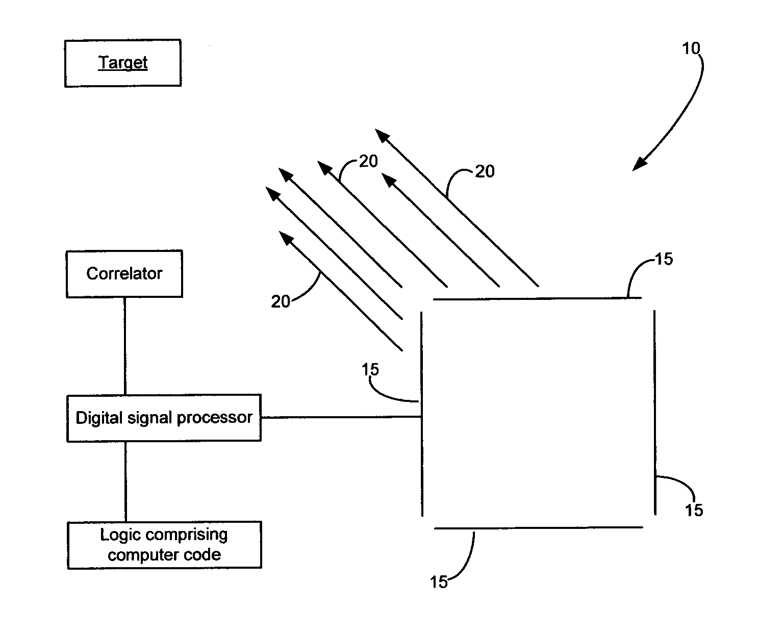
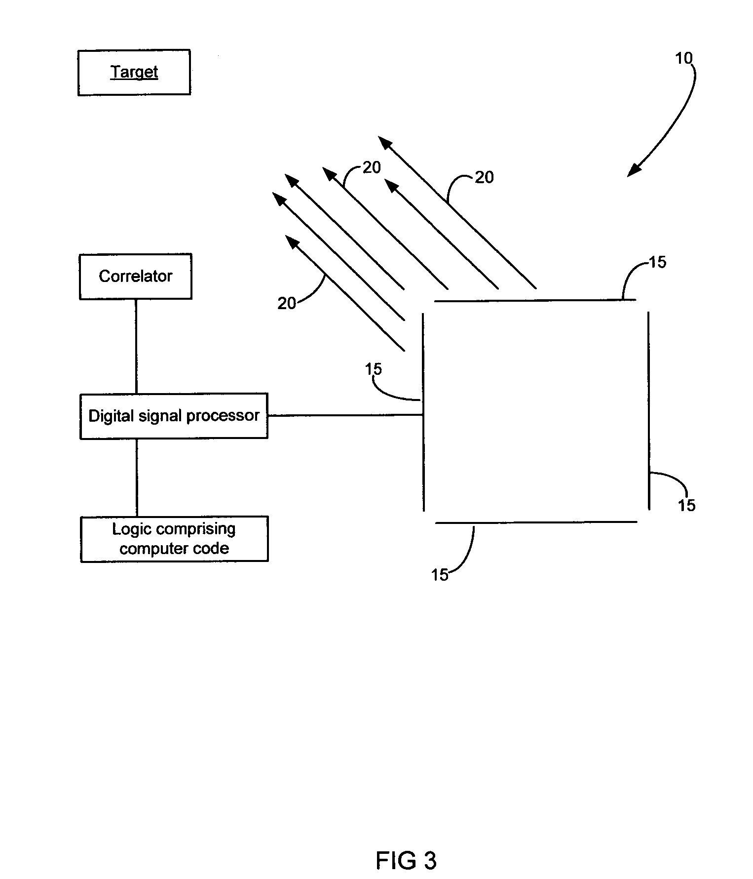
[0018]The present invention relates to the field of ultra-wideband (UWB) communication systems. A preferred embodiment of the present invention employs multiple antenna elements, or multi-element antenna arrays to emit and shape UWB pulses, or wave fronts to maximize available bandwidth in an UWB communication system, while minimizing radiated radio frequency (RF) en...


PUM


Abstract

An ultra-wideband (UWB) antenna array is provided. One embodiment of the present invention employs a multi-element antenna for UWB beam forming and also for time-of-arrival vector processing to resolve multi-path problems in an UWB communication system. Another embodiment of the present invention recovers the energy contained in the multi-path reflections to increase signal-to-noise ratios of received UWB pulses.

Description

[0001]Priority is claimed to U.S. Provisional Application Ser. No. 60 / 338,162, filed Nov. 9, 2001, titled “Method and Apparatus for Transmitting and Receiving Ultra-Wideband Signals,” which is referred to and incorporated herein in its entirety by this reference.FIELD OF THE INVENTION[0002]The present invention generally relates to ultra-wideband (UWB) communication systems. More particularly, the invention concerns a multi-element antenna array for receiving and transmitting UWB signals.BACKGROUND OF THE INVENTION[0003]In the theory, an ultra-wideband (UWB) pulse, or signal, transmitted from a source and received by a target arrives without any delays or distortions caused by the surrounding environment. Such an ideal environment is difficult to realize outside the vacuum of outer space. In more practical environments and especially in urban settings, the environment may have a substantial impact on the received UWB signal.[0004]For example, natural and man-made features, such as b...

Claims


Application Information

Patent Timeline
Patent Type & Authority Patents(United States)
IPC IPC(8): H01Q21/00G01S3/50H01Q3/26H01Q21/20H04B1/18H04B1/69H04B1/7163H04B7/08H04B7/10
CPCG01S3/50H01Q3/2682H04B1/71635H04B1/71637H01Q21/205H04B7/086
Inventor SANTHOFF, JOHN H.HARMUTH, HENNING F.
Owner INTELLECTUAL VENTURES HLDG 73
Why Eureka
Try Eureka