
Method for compensating for remote clock offset

a technology of offset compensation and remote clock, which is applied in the field of oilfield telemetry systems, can solve the problems of insignificant offset due to communication delay, time-consuming and extremely costly, and the need to remove the drilling assembly or "tripped" from the drilled borehol

Inactive Publication Date: 2002-06-04
HALLIBURTON ENERGY SERVICES INC
View PDF12 Cites 121 Cited by
  • Summary
  • Abstract
  • Description
  • Claims
  • Application Information

AI Technical Summary

Problems solved by technology

Any offset due to the communications delay is for all practical purposes insignificant.
The problem with obtaining downhole measurements via wireline is that the drilling assembly must be removed or "tripped" from the drilled borehole before the desired borehole information can be obtained.
This can be both time-consuming and extremely costly, especially in situations where a substantial portion of the well has been drilled.
Typically, drilling rigs are rented by the day at a substantial cost.
Consequently, the cost of drilling a well is directly proportional to the time required to complete the drilling process.
Removing thousands of feet of tubing to insert a wireline logging tool can be an expensive proposition.
For example, it is impractical to run an electrical cable downhole during drilling operations.
If different locations are subjected to varying conditions, such as temperature and pressure, this may result in clock desynchronization.
For LWD techniques where it is desirable to compensate for clock error, this issue has not been adequately addressed.
As mentioned previously, wireline methods have the disadvantage that the drillstring must be tripped, causing delay and expense.
Because the clock is sensitive to temperature, it will drift relative to the surface clock and lose synchronization.
When an accuracy of milliseconds is desired, this drift is unacceptable.
Second, the phase and amplitude of the received signal will be altered, as portions of the signal travel along different paths and interfere with each other at the receiver.
Third, the duration of any portion of the signal will be greater than the duration of that portion originally transmitted, as the variation in path lengths and path velocities will result in signals being received over a range of times. Lastly, reverberation of the tool itself can increase the duration of the received signal.
However, the downhole environment, in particular the altered temperature with respect to the surface, causes drift over the course of several days.
This produces a clock error, leading to erroneous records of time in measurements utilizing the downhole clock.
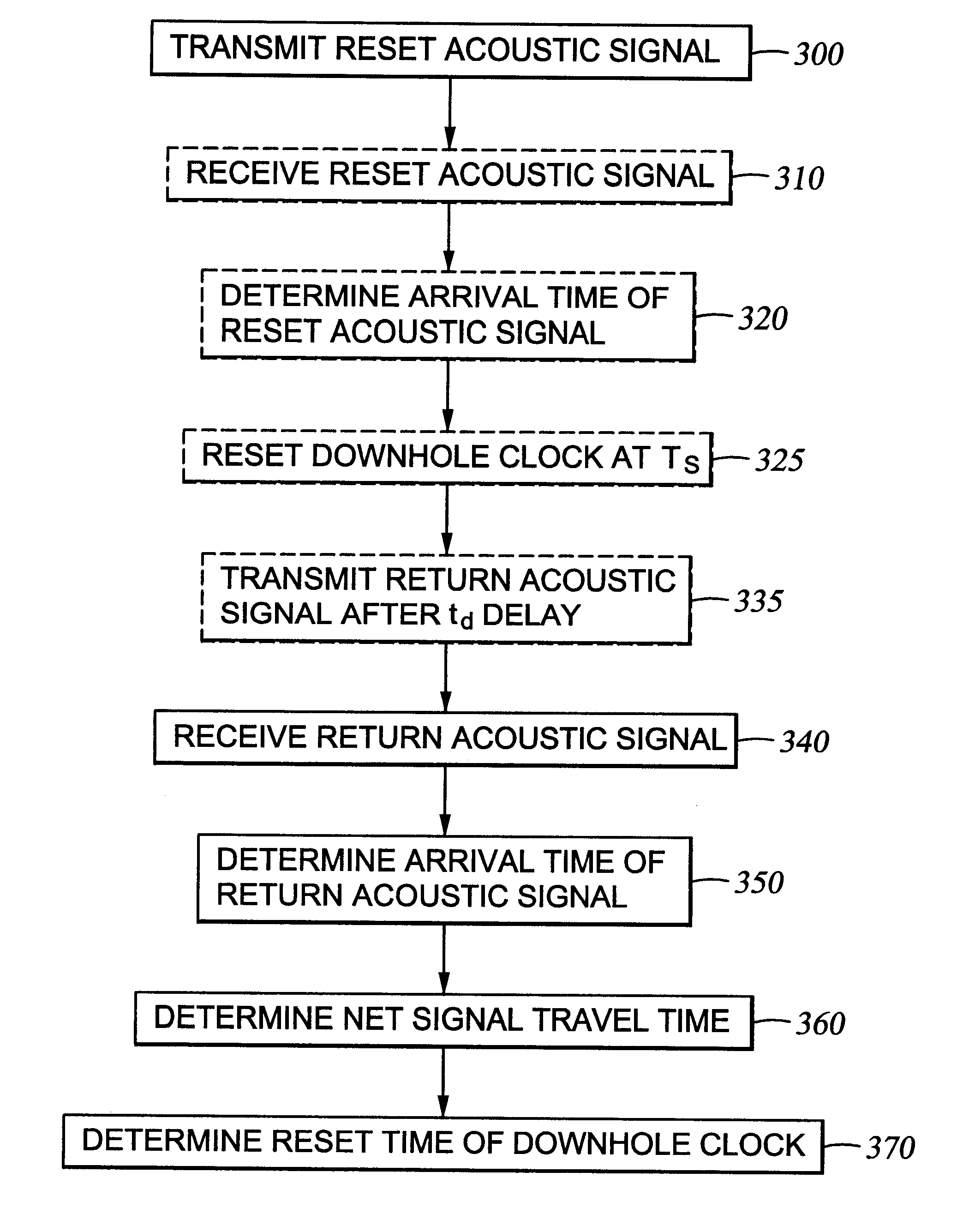
The return acoustic signal is received at the surface after a time .DELTA.t, resulting in a net delay between transmission of the reset acoustic signal and receipt of the return acoustic signal at the surface of 2.DELTA.t+.DELTA.T'.

Method used


Image

  • Method for compensating for remote clock offset
  • Method for compensating for remote clock offset
  • Method for compensating for remote clock offset

Examples


Embodiment Construction

Prototype experiments were conducted at the Halliburton Technology Center, at Carrollton. These experiments were carried out prove the feasibility of downhole clock synchronization. Additionally, these were conducted to study the effect of different depths of the downhole acoustic apparatus on the synchronization accuracy as well as, find the relative compensation accuracy of the two different types of transmitters. Referring now to FIG. 8, a schematic of the experimental set-up is shown. Apparatus 810 includes drop hammer 820. The drop hammer was devised by imparting velocity to a mass of steel using a pneumatic source and acts as the surface transmitter. The mass was allowed to impact on the cross-section of the pipe and thus impart an acoustic impulse in the tubing. Apparatus 810 further includes wireline 830, surface accelerometer 840, acting as the surface sensor, downhole SPCA transmitter 850, and downhole accelerometer 860, acting as the downhole sensor. Referring to FIG. 9, ...


PUM


Abstract

A system is disclosed for synchronizing a clock in a well containing a drill string with a clock located near the surface of the well. The system includes devices for transmitting and receiving a pair of acoustic signals between locations associated with each clock and processing those signals. The system determines the time of arrival of each acoustic signal by analyzing the shape of a function of the acoustic signal chosen from a group of functions suitable to determine a clock offset with millisecond accuracy.

Description

1. Field of the InventionThe present invention generally relates to oilfield telemetry systems, and more specifically relates to a method for compensating for offset between a downhole clock and a clock in a surface installation.2. Description of Related ArtModem petroleum drilling and production operations demand a great quantity of information relating to parameters and conditions downhole. Such information typically includes characteristics of the earth formations traversed by the wellbore, along with data relating to the size and configuration of the borehole itself. The collection of information relating to conditions downhole, which commonly is referred to as "logging", can be performed by several methods.In conventional oil well wireline logging, a probe or "sonde" housing formation sensors is lowered into the borehole after some or all of the well has been drilled, and is used to determine certain characteristics of the formations traversed by the borehole. The upper end of ...

Claims


Application Information

Patent Timeline
IPC IPC(8): E21B47/12E21B47/16G01V1/26G01V1/00G04G7/00H04L7/02
CPCE21B47/16G04G7/00G01V1/26H04L7/007
Inventor SHAH, VIMAL V.MINEAR, JOHN W.MALLOY, ROBERTBIRCHAK, JAMES R.GARDNER, WALLACE R.ROBBINS, CARL
Owner HALLIBURTON ENERGY SERVICES INC
Learn More