
Sampling Rate Conversion System

a conversion system and signal technology, applied in the field of signal processing, can solve the problems of system needing a long computing time to perform calculations, severe limiting speech quality, and large amount of resources, and achieve the effects of reducing signal processing burden, reducing computing time and memory resources, and reducing processing and memory resources

Active Publication Date: 2008-06-26
CERENCE OPERATING CO
View PDF3 Cites 11 Cited by
  • Summary
  • Abstract
  • Description
  • Claims
  • Application Information

AI Technical Summary

Benefits of technology

[0009]A sampling rate conversion system decreases signal processing burden on cellular phones, headsets, and other electronic devices. Such devices may have limited processing, memory, and power resources. The conversion system in the device may consume significantly less computing time and memory resources to convert between sampling rates. Relieved of some of the signal processing burden, the device may instead execute other useful tasks and operations.

Problems solved by technology

In the context of telephony, signals are often band limited to between less than 300 Hz to 3.4 kHz, thereby severely limiting speech quality.
These systems and methods may require a large amount of resources.
Some systems may need a long computing time to perform calculations.
Other systems may require a large amount of memory to store sample information.
Thus, sampling rate conversion remains a significant problem in modem signal processing systems and in modem devices that often have severely limited processing capability, memory resources, and power reserves.
Such devices may have limited processing, memory, and power resources.
The conversion system in the device may consume significantly less computing time and memory resources to convert between sampling rates.

Method used


Image

  • Sampling Rate Conversion System
  • Sampling Rate Conversion System
  • Sampling Rate Conversion System

Examples


Embodiment Construction

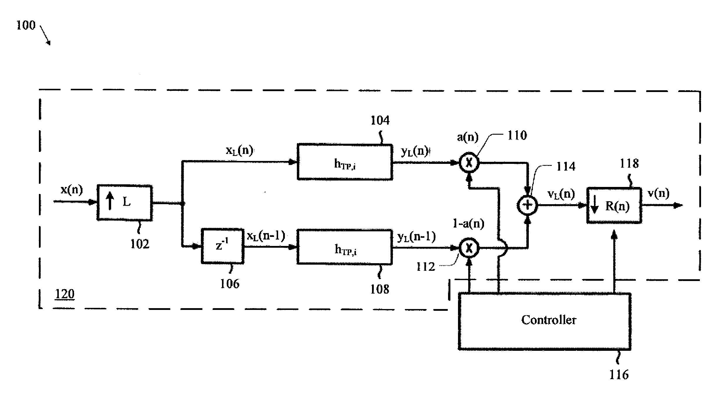
[0022]A sampling rate conversion system adapts the sampling rate of an input signal into a different sampling rate for an output signal. The input signal may be a digital signal sampled from an analog signal at an input signal sampling rate. The system may generate an output signal from the input signal using logic that implements up-sampling, filtering, time-delaying, weighting, adding, and other operations. The system may also filter the signal during processing using a low-pass filter that may be a finite impulse response filter. The system may also down-sample an intermediate signal (such as the signal obtained by the adder) to produce the output signal. The system may generate time-dependent sampling rates for the output signal and / or the input signal by using buffers or other logic. The sampling rate conversion system may use a relatively small amount of computing resources and memory, thereby freeing the device that processes the signal to devote more resources to other usefu...


PUM


Abstract

A sampling rate conversion system reduces the signal processing burdens carried by cellular phones, headsets, and other electronic devices. Because the system consumes fewer resources to convert between signal sampling rates, the system may significantly reduce processing time and resource requirements in the device. As a result, the device may instead devote resources to performing other useful tasks, such as interacting with the user through a graphical user interface and performing selected processing tasks.

Description

1. PRIORITY CLAIM[0001]This application is a continuation of U.S. patent application Ser. No. 11 / 657,408, filed Jan. 24, 2007, which claims the benefit of priority from European Patent Application No. 06001452.9, filed Jan. 24, 2006, both of which are incorporated by reference herein.BACKGROUND OF THE INVENTION[0002]1. Technical Field[0003]This disclosure relates to signal processing, and in particular, to sampling rates of signals.[0004]2. Related Art[0005]Electronic devices that communicate with one another process signals at different sampling rates. To use a signal, a device may need to convert a signal having one sampling rate into a signal having a different sampling rate. For instance, a Bluetooth headset for a cellular phone may up-sample the signal obtained from the cellular phone before the headset further processes the signal. In the context of telephony, signals are often band limited to between less than 300 Hz to 3.4 kHz, thereby severely limiting speech quality. Accor...

Claims


Application Information

Patent Timeline
Patent Type & Authority Applications(United States)
IPC IPC(8): H03K5/159
CPCH03H17/0685H03H17/0642
Inventor SCHMIDT, GERHARD UWEKRINI, MOHAMEDROSSLER, MARTIN
Owner CERENCE OPERATING CO
Learn More