Transfer apparatus, method of manufacturing the transfer apparatus and image forming apparatus using the transfer apparatus

a technology of transfer apparatus and manufacturing method, which is applied in the direction of piezoelectric/electrostrictive/magnetostrictive devices, electrographic process apparatus, instruments, etc., can solve the problems of high cost, mutual interference preventing individual resonators from having uniform vibration characteristics, and inability to supply vibration energy to the toner image supporting body between the adjacent horns. , to achieve the effect of superior toner transfer and high cos

Inactive Publication Date: 2008-06-26
RICOH KK
View PDF5 Cites 16 Cited by
  • Summary
  • Abstract
  • Description
  • Claims
  • Application Information

AI Technical Summary

Benefits of technology

[0024]In general, a Langevin oscillator tightened with bolts is used as the ultrasonic oscillator. Oscillators of this type are aligned. To drive a single Langevin oscillator, 70 to 140 W of electric power is needed, so hundreds of watts is needed to support the 20-inch width. Therefore, a power supply of high frequency and high voltage operating at a frequency of20 kHz or higher is required, resulting in a high cost.
[0025]The present invention addresses the above problem involved in th

Problems solved by technology

This raises a problem that mutual interference (a phenomenon called cross coupling) is caused when a plurality of resonators are driven.
In this case, however, vibration energy cannot be supplied to the toner image supporting body between the adjacent horns.
When a plurality of resonators

Method used


Image

  • Transfer apparatus, method of manufacturing the transfer apparatus and image forming apparatus using the transfer apparatus
  • Transfer apparatus, method of manufacturing the transfer apparatus and image forming apparatus using the transfer apparatus
  • Transfer apparatus, method of manufacturing the transfer apparatus and image forming apparatus using the transfer apparatus

Examples


first embodiment

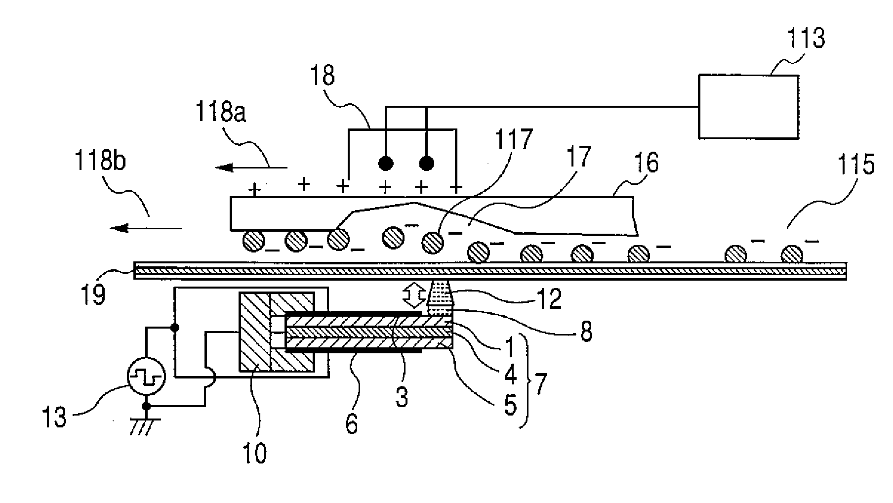
[0115]FIG. 1 illustrates the structure of a transfer apparatus in a first embodiment of the present invention, in which a toner image made of toner 115, 117 and formed on the OPC photosensitive belt 19 is transferred to roughened surface paper or a second surface used in double-sided printing. The paper 16 includes a void 17 with a depth of 20 to 30 μm and a width of 50 to 100 μm on the surface. The toner 115, 117 is negatively charged; its particle is 9 μm in diameter. The transfer apparatus is a continuous paper printer with a process speed (vector movement speed) of 23 ips; it adapts to paper 16 with a width of 20.5 inches, the printing width being 19.5 inches. The vibrating unit is formed by changing the piezoelectric bimorph element 7 illustrated in FIG. 5 to the cantilever structure illustrated in FIGS. 8(a) and 8(b). During non-driving, the protrusion portion 12 is apart from the backside of the belt 11. The shim member 4 of the piezoelectric bimorph element 7 is a stainless ...

second embodiment

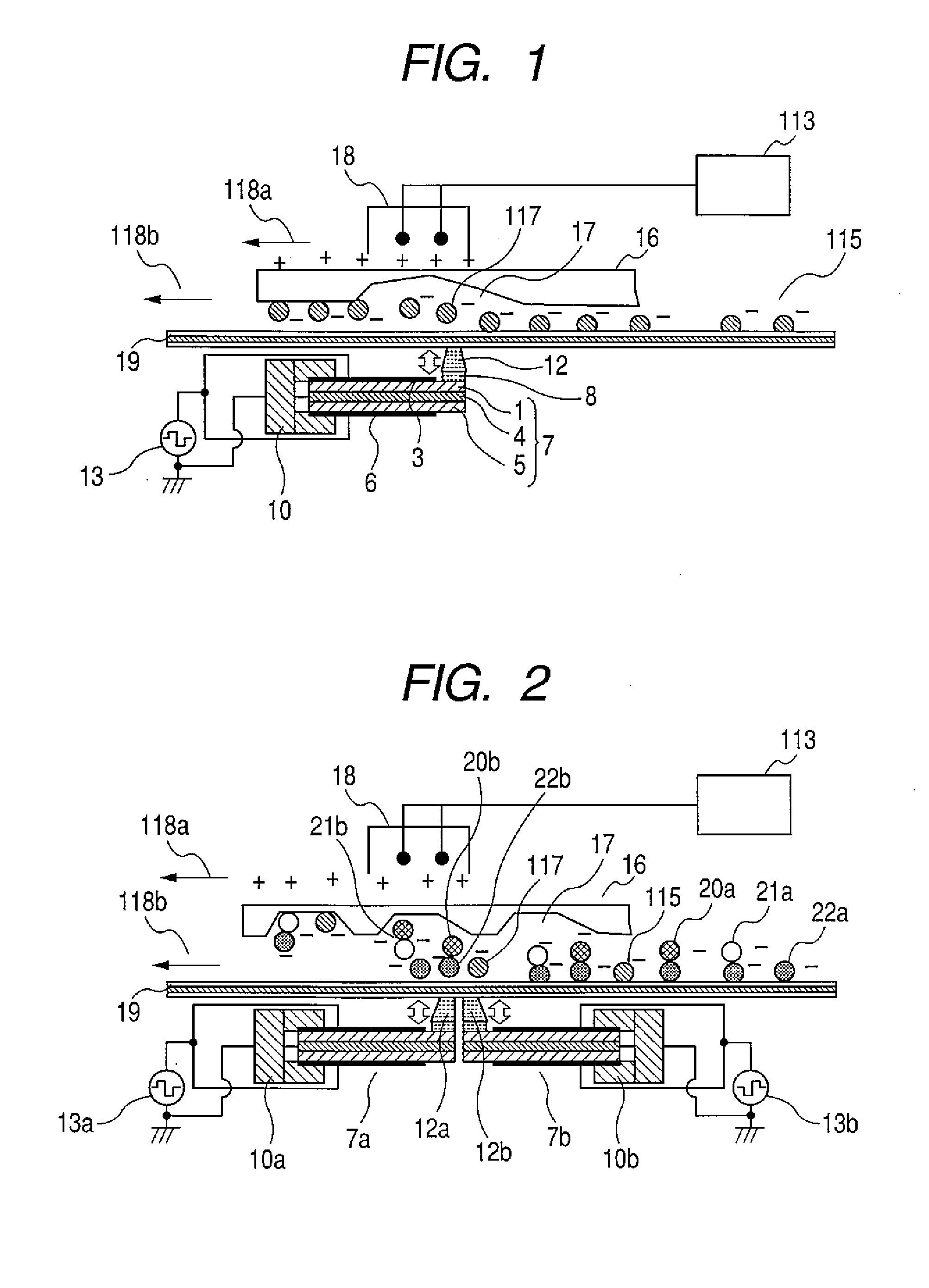
[0117]FIG. 2 is a structural diagram illustrating the transfer apparatus according to the second embodiment of the present invention. The drawing shows the structure of the apparatus that transfers a color toner image to the front surface of an embossed paper 16, the color toner image being formed on the intermediate transfer belt 19 made of polyimide resin by overlapping toners 20a, 21a, 22a and 115 in four colors, yellow (Y), magenta (M), cyan (C), and black (K). Many voids 17 in various shapes are formed on the surface of the embossed paper 16. Accordingly, to have each toner 20a, 21a, 22a and 115 comprising a plurality of layers fly from the intermediate transfer belt 19 and transfer to the surface of a void, a great inertia force must be applied to the toner 20a, 21a, 22a and 115. The toner 20a, 21a, 22a and 115 is a negatively charged toner with a particle diameter of 9 μm. The printer is a continuous paper printer with a print density of 600 dpi and a process speed (vector mo...

third embodiment

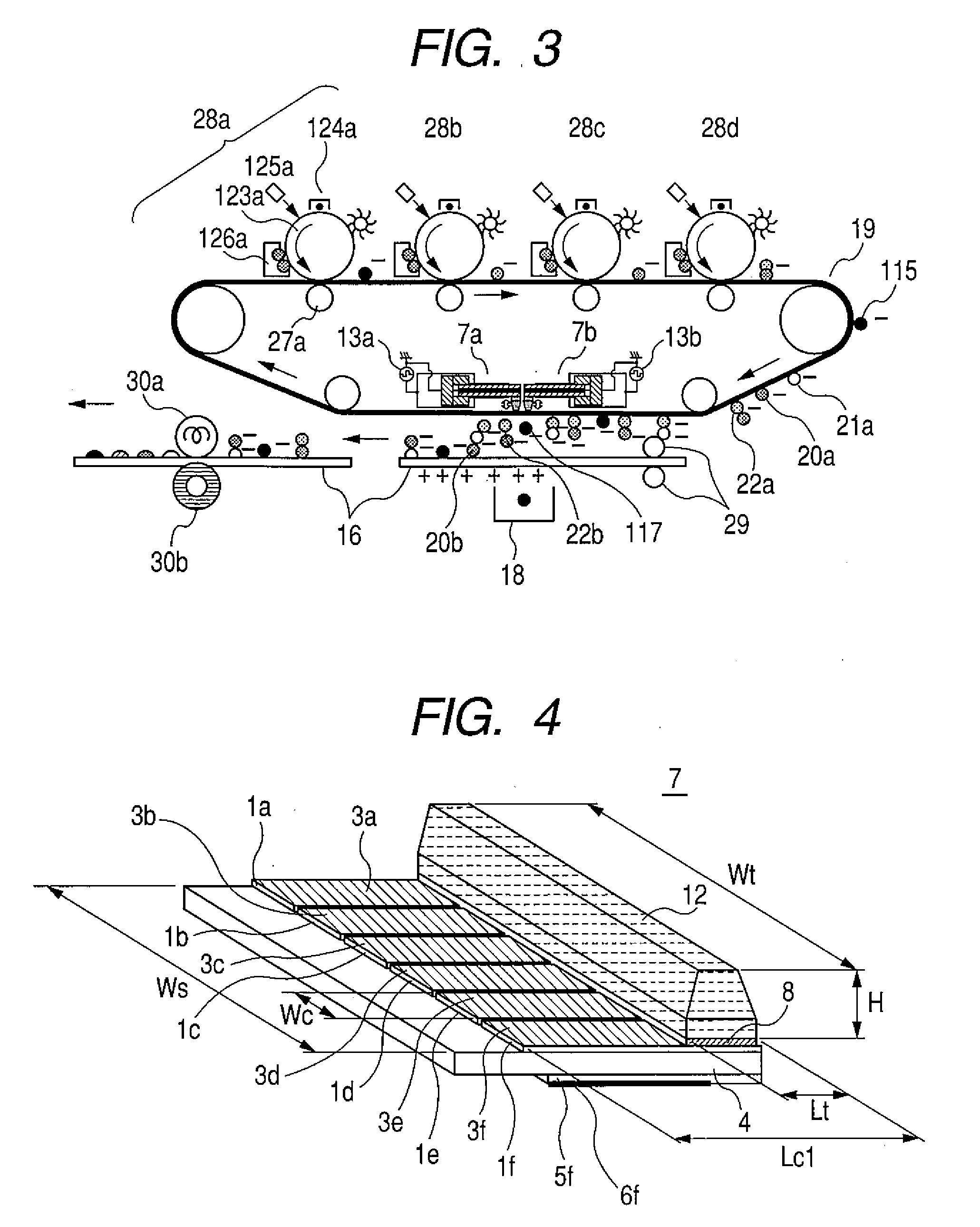
[0118]FIG. 3 is a structural diagram illustrating an image forming apparatus in which the transfer apparatus in the present invention is used. The K toner image forming part 28a, C toner image forming part 28b, M toner image forming part 28c, and Y toner image forming part 28d have basically the same structure except that they use different developers. Therefore, only the structure of the K toner image forming part 28a will be described below. The OPC photosensitive drum 123a is charged by the charger 124a, after which an electrostatic latent image corresponding to a print image is formed by the exposing part 125a. The developing unit 126a then forms a K toner image on the photosensitive drum. The toner 20a, 21a, 22a or 115 is negatively charged, so the toner image is transferred to the intermediate transfer belt 19 by the transfer roll 30a to which a positive voltage has been applied. A C toner image, M toner image, and Y toner image are transferred to the rotating intermediate tra...


PUM


Abstract

A transfer apparatus comprises a toner image supporting body and a corona transfer means, which are oppositely disposed, and a vibrating unit for exerting vibration force to the rear face of a toner supporting body, disposed opposite to the corona transfer means, wherein the vibrating unit has a cantilever structure for holding an end of a piezoelectric bimorph element in which a pair of piezoelectric bodies each having an electrode, are bonded to both sides of a conductive elastic member (a shim member). A protrusion portion is provided on the other end of the piezoelectric bimorph element.

Description

CLAIM OF PRIORITY[0001]The present application claims priority from Japanese application serial No. 2007-148123, filed on Jun. 4, 2007, which claims priority from Japanese patent application serial No. 2006-348106, filed on Dec. 25, 2006, the contents of which are hereby incorporated by reference into this application.BACKGROUND OF THE INVENTION [0002]1. Field of the Invention[0003]The present invention relates to a transfer apparatus, a method of manufacturing the transfer apparatus and an image forming apparatus using the transfer apparatus.[0004]2. Description of Related Art[0005]An image forming apparatus using the electronic photographic method transfers a toner image formed on a toner image supporting body such as a photosensitive belt or an intermediate transfer body, to a recording medium, and melts and fixes the toner image on the surface of the recording medium by using a fixing device. FIGS. 14(a) and 14(b) illustrate a conventional transfer apparatus; negatively charged ...

Claims


Application Information

Patent Timeline
IPC IPC(8): G03G15/16H01L41/08H01L41/09H01L41/187H01L41/193H01L41/22H01L41/257H01L41/29H01L41/313H01L41/45
CPCG03G15/0131G03G2215/0129G03G15/161
Inventor UMEDA, TAKAOMABUCHI, HIROYUKIOOHARA, SHUNICHI
Owner RICOH KK
Why Eureka
Try Eureka