Single Layer Overhead Full Interchange Flyover
a flyover and single layer technology, applied in the field of overpasses, can solve the problems of occupying too much space, affecting the safety of residents, and inconvenience of drivers with extra long ramps, and achieve the effects of reducing noise, reducing waste of exhaust, and saving energy
- Summary
- Abstract
- Description
- Claims
- Application Information
AI Technical Summary
Benefits of technology
Problems solved by technology
Method used
Image

Examples
example 1
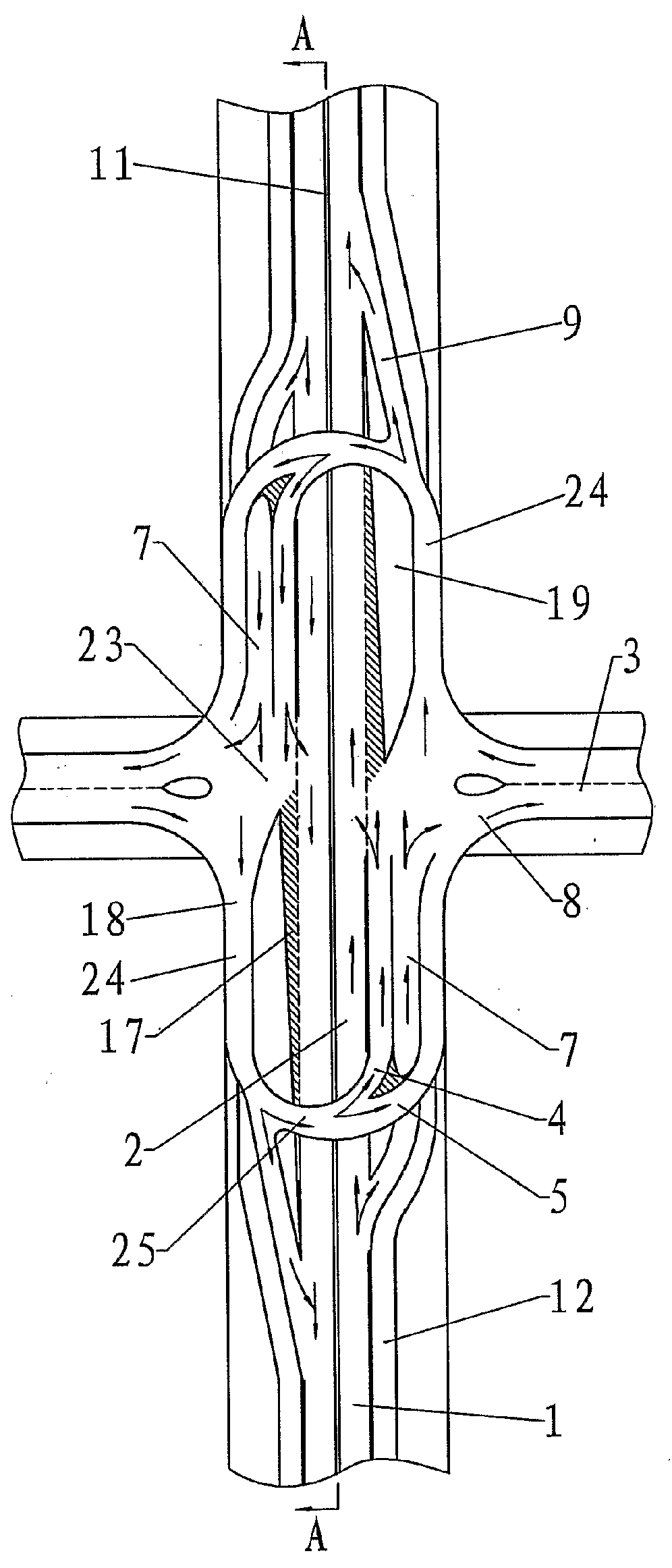
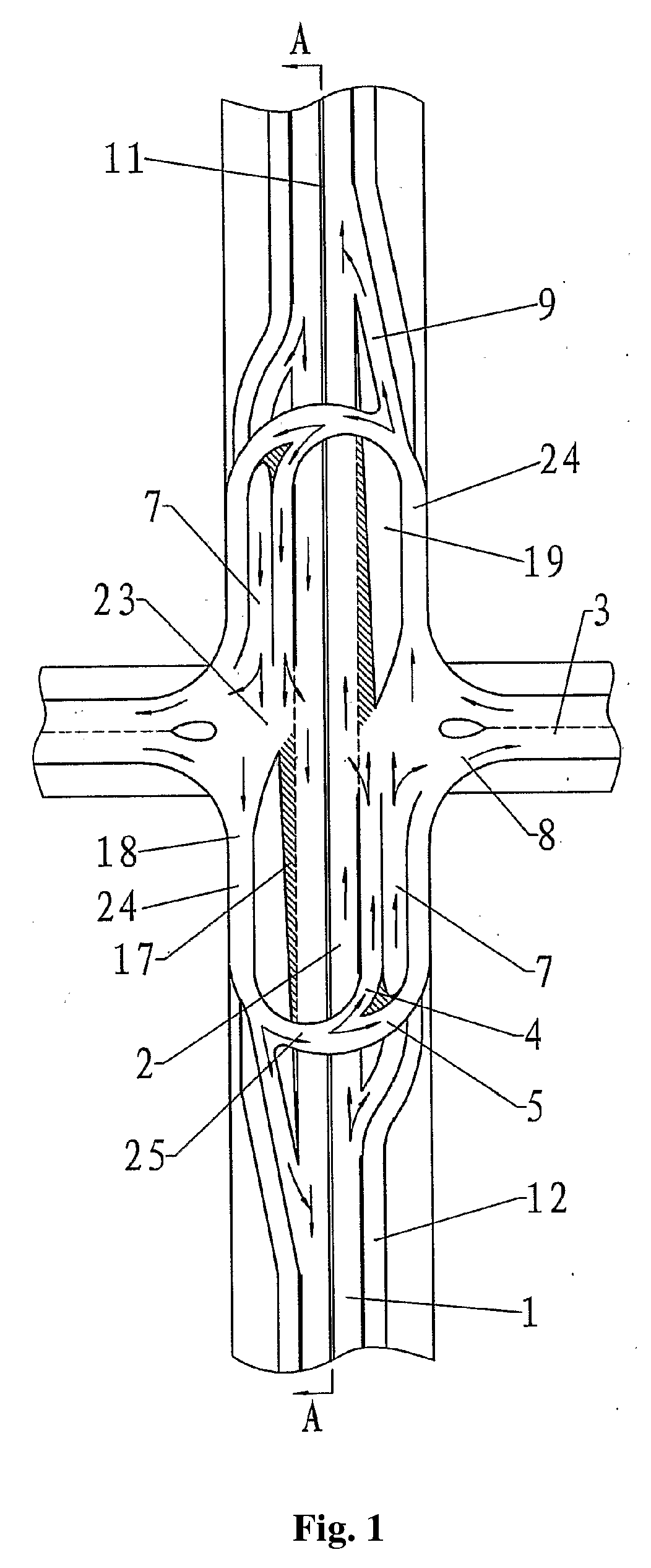
[0018]As shown is FIG. 1, an overpass is provided at an intersection. The intersection is divided into the upper, lower, left, and right roads in which the main road 1 accommodates vehicle flow in the upper and lower direction, and the intersected road 3 accommodates vehicle flow in the left and right direction. The four roads of the overpass are leveled with the driveway's surface and are connected therewith. The straight main road 1 on the overpass is the arched separated bridge 2 which has the highest height at a position where the main road 1 intersects the intersected road 3. There is a ramp extending from the highest point of the arched separated bridge 2 down the upper and lower direction to connect it in the direction of the main road 1. The semi-ramped overhead bridge stages 8 are provided at the left and the right of the intersected road 3 at both sides of the arched separated bridge 2. One end of the semi-ramped overhead bridge stage 8 is connected with the arched separat...
example 2
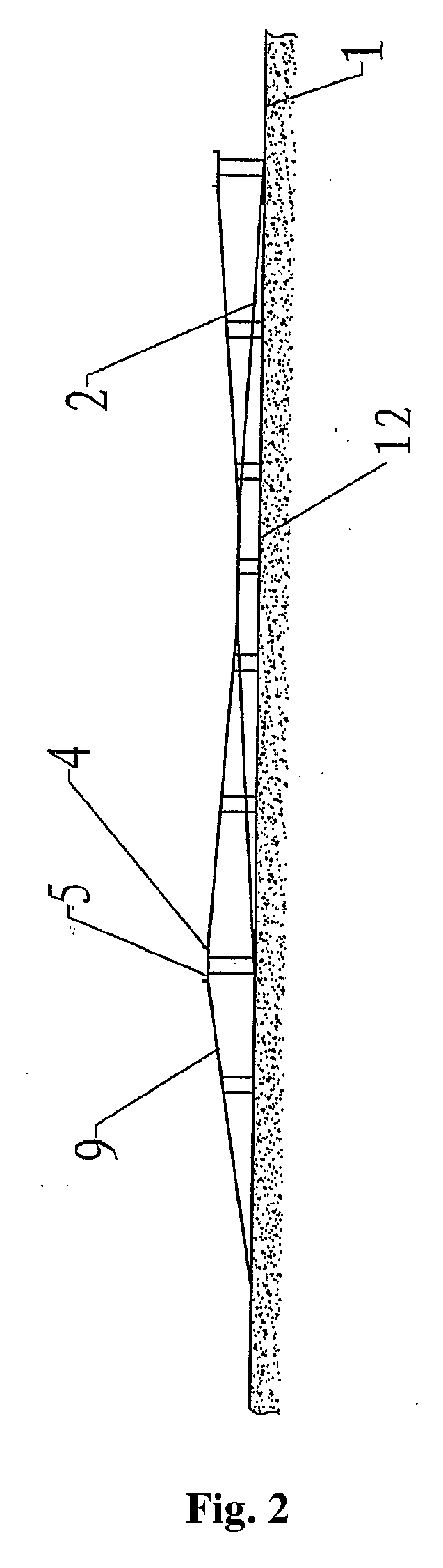
[0028]The U-shaped circle road 24 is relatively long because the ramp length of the arched separated bridge 2 must satisfy the regulation of the ramp of the driveway and ensure clearance between the arcuate part 25 of the U-shaped circle road 24 and the arched separated bridge 2. As shown in FIG. 2, in order to shorten the length of the U-shaped circle road 24, construction of the embodiment 1 is partially modified by allowing the height of the arcuate part 25 of the U-shaped circle road 24 to exceed the height of the connection platform 23, so that the combination of the upper and lower U-shaped circle roads 24 has a saddle-like shape. Thus, in order to shorten the length of the U-shaped circle road 24, vehicles will enter an up-ramp when traveling from the connection platform 23 onto the U-shaped circle road 24, and will enter a down-ramp when traveling from the U-shaped circle road 24 onto the connection platform 23.
[0029]Because vehicles enter an up-ramp after entering the entra...
example 3
[0031]As shown in FIG. 3 in order to reduce the driving distance of vehicles turning around on the intersected road 3 in embodiments 1 and 2, medians 26 for turning around are provided on the left and right connection platforms 23, respectively. The median 26 for turning around separates the connection platform 23 into the straight transit driveway 27 between the upper and lower U-shaped circle roads 24 and the U-turn driveway 28, which not only ensures a straight-way driving between the upper and lower U-shaped circle roads 24, but also allows vehicles turning around on the intersected road 3 to enter the on-ramp through the U-turn driveway 28 directly after entering the connection platform 23 from the off-ramp, thus decreasing the turnaround distance on the U-shaped circle road 24.
[0032]If the topographic condition permits or if there is a need to expand capacity, an underpass tunnel 6 in the direction of the left and right intersected road 3 can be added beneath the walking way s...
PUM
 Abstract
Description
Claims
Application Information
 - Generate Ideas
- Intellectual Property
- Life Sciences
- Materials
- Tech Scout
- Unparalleled Data Quality
- Higher Quality Content
- 60% Fewer Hallucinations
Browse by: Latest US Patents, China's latest patents, Technical Efficacy Thesaurus, Application Domain, Technology Topic, Popular Technical Reports.
© 2025 PatSnap. All rights reserved.Legal|Privacy policy|Modern Slavery Act Transparency Statement|Sitemap|About US| Contact US: help@patsnap.com