Connector for connecting sheet piles

a technology of connecting sheet piles and connecting profiles, which is applied in the direction of bulkheads/piles, haberdashery, etc., can solve the problems of large bending and torsional stresses of the connecting profile, and achieve the effect of reducing the bending and torsional stresses, facilitating the pre-assembly of the connecting profile, and ensuring the connection

Inactive Publication Date: 2008-06-26
SHEET PILE LLC
View PDF0 Cites 30 Cited by
  • Summary
  • Abstract
  • Description
  • Claims
  • Application Information

AI Technical Summary

Benefits of technology

[0012]Alternatively, it is suggested to design the connecting profile of the invention as a weld-on connector by providing that side of one of the hooked profiles which is turned away from the hooked section with a flattened weld surface. The connecting profile can then be welded on corresponding carrier elements, such as double T-beams, or tubular piles, or even on adjacent sheet piles. Both hooked profiles are preferably provided with corresponding weld surfaces so that the installation position of the connecting profile need not be taken into consideration when welding the connecting profile. This additionally simplifies the pre-assembly of the connecting profile on a carrier element.
[0013]In a particularly preferred embodiment, the connecting profile for interconnecting sheet piles is designed with so-called Larssen locks. For this purpose, each hooked profile comprises a substantially straight connecting section, which extends at least approximately at right angles in relation to the central strip and merges into the hooked section. The hooked section extends in a manner that is curved by at least approximately 180° so that its free end points to the central strip and forms an opening with the latter to hook in the lock. Both the openings of the hooked profiles point toward opposite directions. The hooked profile thus designed is firstly suitable for hooking the aforementioned Larssen locks securely and easily, and secondly permits sufficient swivel movements of the Larssen locks in the hooked profile.
[0014]Since the forces acting on the hooked profile bring about corresponding bending moments, particularly in the transition of the connecting section into the central strip, it is suggested according to the present invention to provide the connecting profile with appropriately massive dimensions particularly at this transition. For this purpose, it is suggested to design the connecting section or at least that side of one of the two hooked profiles which is turned away from the inner chamber and points outwardly in such a way that the side merges flush into one of the longitudinal edges of the central strip. In this way an accumulation of material is achieved in the region of the transition, thereby imparting special strength to the hooked profile in this particularly stressed section.
[0015]In order to improve the diversion of the tensile stresses acting on the hooked profile into the central strip, it is further suggested to design the inner chamber of every hooked profile in such a way that the central strip merges into the connecting section forming a radius. This design measure firstly enables the diversion of the occurring tensile stresses into the central strip in an undisturbed manner and secondly enables the corresponding material accumulation in the region of the transition of the connecting section into the central strip, thereby also increasing the strength of the connecting profile in this particularly stressed section.
[0016]It is further suggested that the inner chamber of each hooked profile be provided with an oval cross-section so that the Larssen lock hooked into the hooked profile can swivel back and forth within the largest possible range in the hooked profile.

Problems solved by technology

However, the mirror-inverted arrangement of the hooked profiles involves a problem in the connecting profile known from the prior art.
The tensile forces caused by the hooked locks and acting along the main coupling directions act on the connecting profile at a distance from each other and thus cause large bending and torsional stresses in the connecting profile that have to be absorbed by the latter.

Method used


Image

  • Connector for connecting sheet piles
  • Connector for connecting sheet piles
  • Connector for connecting sheet piles

Examples


Embodiment Construction

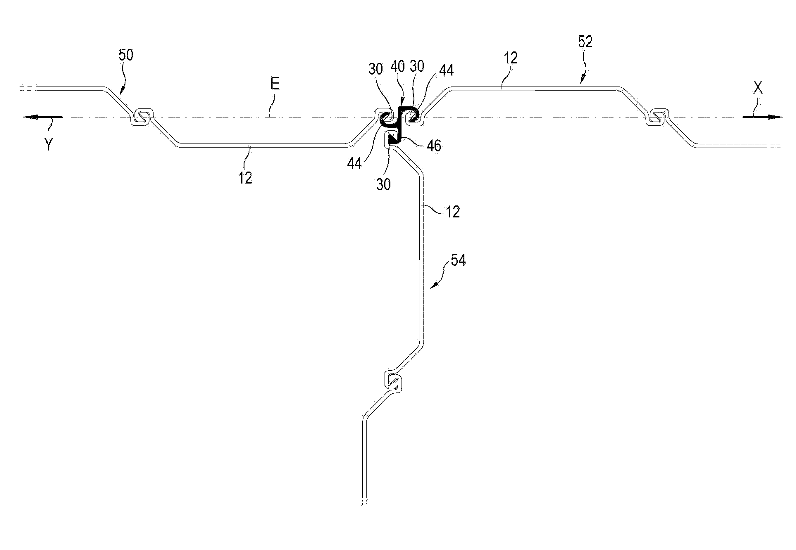
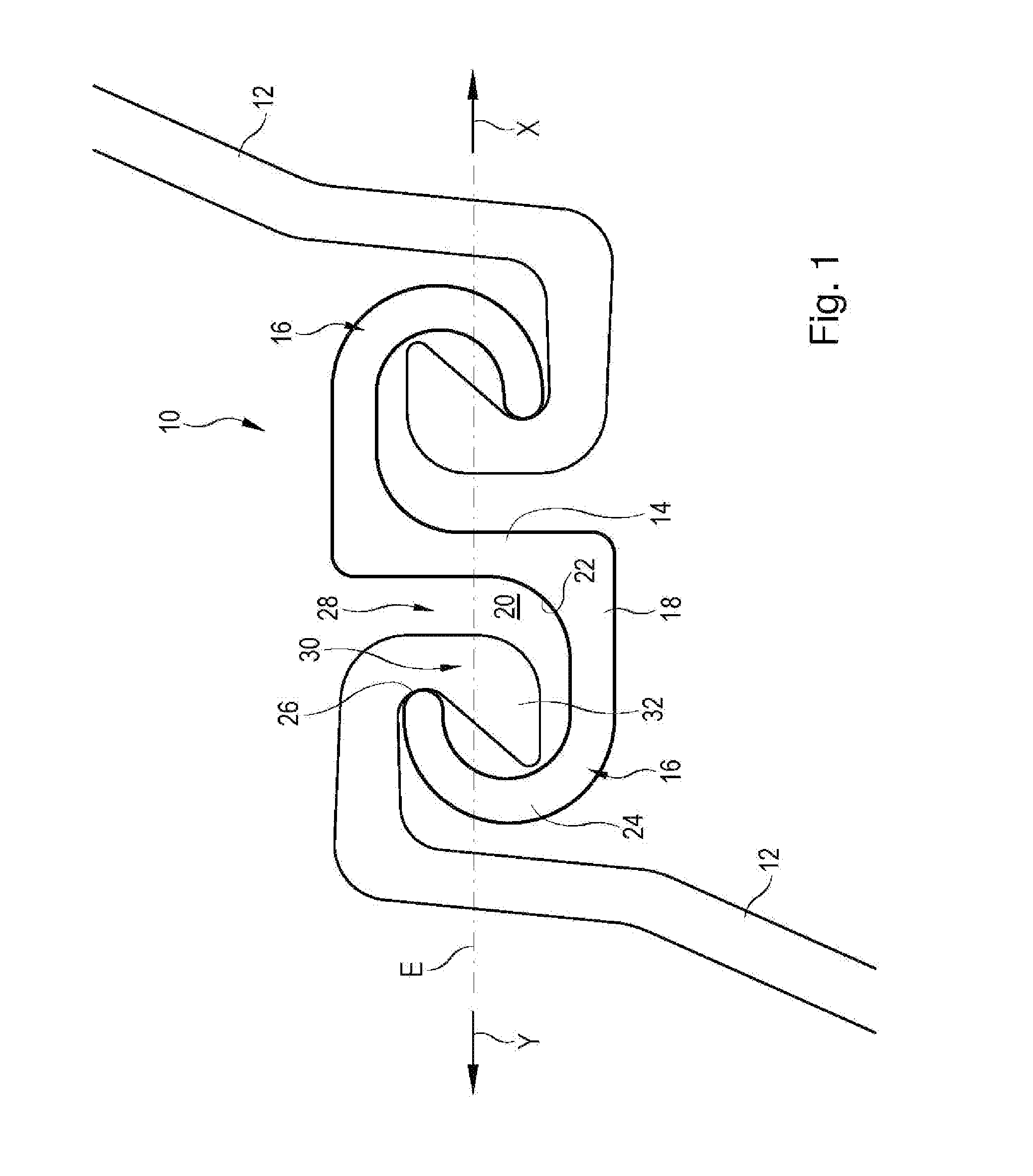
[0021]FIG. 1 is a plan view of a first exemplary embodiment of a connecting profile 10 of the invention for interconnecting two Larssen sheet piles 12 along two main coupling directions X and Y.

[0022]The connecting profile 10 has a central strip 14, on which two identically designed hooked profiles 16 are provided. Each hooked profile 16 has a substantially straight connecting section 18, which extends approximately at right angles to the flat side of the central strip 14. That side of the connecting section 18 which points outwardly is flat and merges flush into the longitudinal edge of the central strip 14. That side of the connecting section 18, which delimits the inner chamber 20 merges into the flat side of the central strip 14 forming a radius 22. This design firstly increases the strength of the transition between the connecting section 18 and the central strip 14 and secondly diverts the forces acting on the hooked profile 16 uniformly into the central strip 14.

[0023]The con...


PUM


Abstract

A connecting profile of substantially uniform cross-section for interconnecting sheet piles. The connecting profile includes a central strip, from which two identical hooked profiles for hooking the locks of two sheet piles in a laterally reversed manner project in opposing main coupling directions. The hooked sections of the hooked profiles extend in a mirror-inverted manner in relation to each other. The two hooked profiles are offset relative to each other on the central strip in such a way that the main coupling directions of the sheet piles hooked into the connecting profile extend at least approximately in a common plane, when the locks engaged with the hooked sections take up the largest axial distance along the main coupling directions in relation to each other.

Description

FIELD OF THE INVENTION[0001]The invention relates to a connecting profile of uniform cross-section for interconnecting sheet piles, which connecting profile comprises a central strip, from which two identical hooked profiles for hooking the locks of two sheet piles in a laterally reversed manner project in opposing main coupling directions, the hooked sections of the hooked profiles extending in a mirror-inverted manner in relation to each other.BACKGROUND OF THE INVENTION[0002]Connecting profiles of the aforementioned type are known from the prior art and have also been disclosed in DE 103 18 769 A1. Such connecting profiles are used inter alia when putting up a bulkhead composed of several sheet piles that are to be interconnected in a straight line in order to be able to compensate for positional deviations that could occur between the sheet-pile wall sections to be interconnected.[0003]For this purpose, the connecting profile is provided with two identical hooked profiles, which...

Claims


Application Information

Patent Timeline
Patent Type & Authority Applications(United States)
IPC IPC(8): E02D5/02A44B13/00
CPCE02D5/06Y10T24/3485E02D5/08
Inventor HEINDL, RICHARD
Owner SHEET PILE LLC
Why Eureka
Try Eureka