Nodal Member For A Frame Structure Nodal Assembly

a nodal member and frame structure technology, applied in the direction of non-disconnectible pipe joints, manufacturing tools, transportation and packaging, etc., can solve the problems of incomplete filling with adhesive and only partially forced air in the pipe, and achieve the effect of simplifying the pre-assembly of the vehicle frame structur

Inactive Publication Date: 2011-06-30
DEERE & CO
View PDF16 Cites 38 Cited by
  • Summary
  • Abstract
  • Description
  • Claims
  • Application Information

AI Technical Summary

Benefits of technology

[0014]Preferably, the fastening flange of the nodal member has a tapering outer contour, so that simplified pre-assembly of the vehicle frame structure through loose positioning or pushing into each other of the frame members and nodal members is possible. The tapering outer contour can particularly be shaped conically.

Problems solved by technology

Because of the self-contained design of the distribution channel there is the possibility that the air present therein is only partially forced out when the adhesive is injected.
Ultimately, this results in incomplete filling with adhesive of the distribution channel and thus fluctuating bonding results.

Method used


Image

  • Nodal Member For A Frame Structure Nodal Assembly
  • Nodal Member For A Frame Structure Nodal Assembly
  • Nodal Member For A Frame Structure Nodal Assembly

Examples


Embodiment Construction

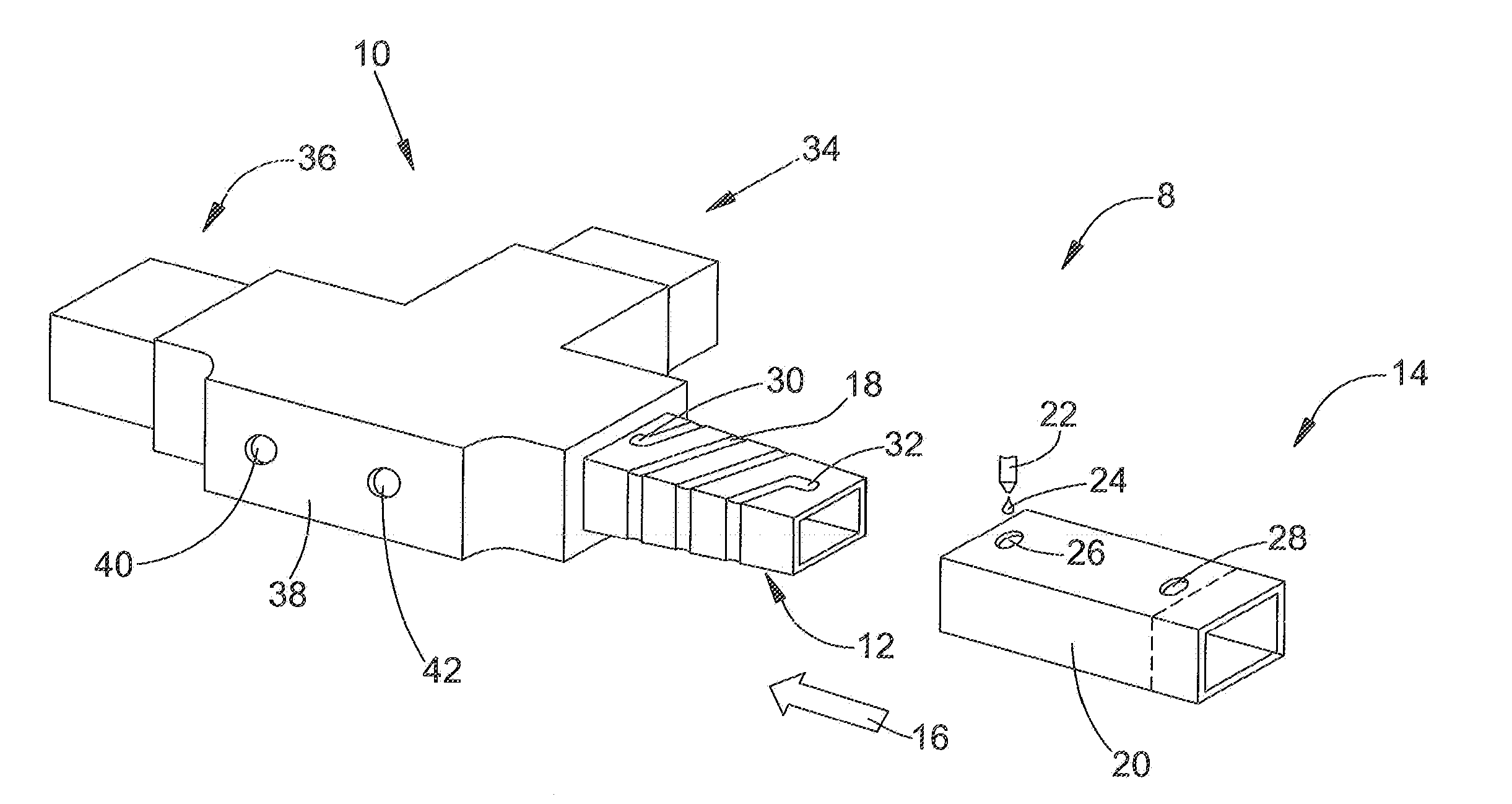
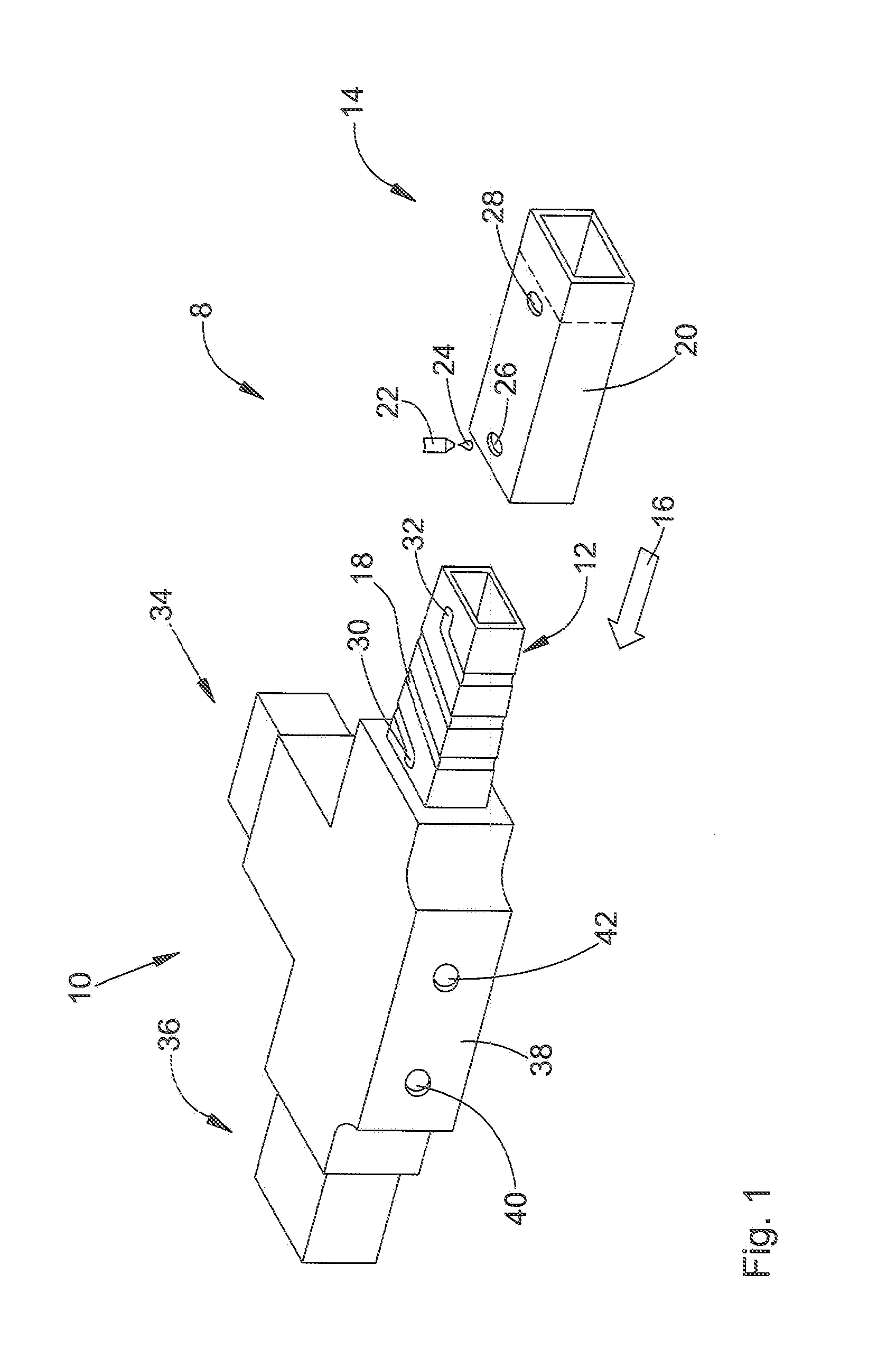
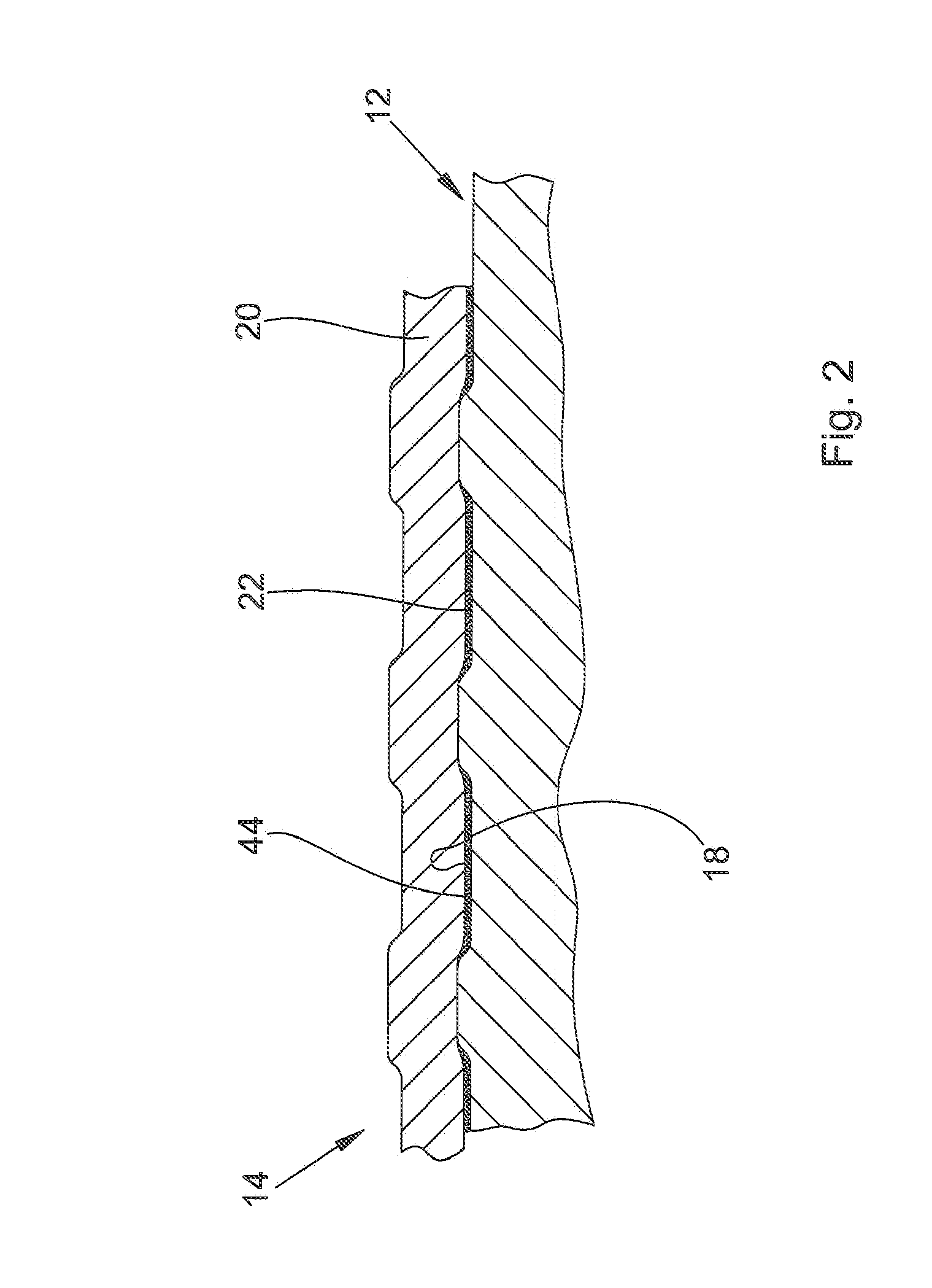
[0019]Referring to FIG. 1, a frame or nodal assembly 8 includes nodal member 10 for coupling to a hollow frame member 14. The nodal member 10 includes at least one fastener flange 12 for connecting with the hollow frame member 14. An adhesive channel 18 runs around the flange 12 in a direction substantially transversely to a pushing-on direction 16 of the frame member 14. For example, the adhesive channel 18 runs around the outer surface of the flange 12. With respect to the pushing-on direction 16 of the frame member 14, the flange 12 has a substantially rectangular cross sectional shape. Frame member 14 includes a fastening region 20 which receives the flange 12 and which also has a corresponding rectangular cross sectional shape. The inside of the frame member 14 is seamlessly drawn from a suitable steel alloy with a smooth finish, at least in the fastening region 20.

[0020]Frame member 14 includes an adhesive injection opening 26 and an adhesive inspection opening 28. The adhesiv...


PUM

PropertyMeasurementUnit
adhesiveaaaaaaaaaa
shapeaaaaaaaaaa
circumferenceaaaaaaaaaa

Abstract

A nodal assembly, such as for a frame structure, includes a nodal member which has a fastening flange for connecting to a hollow frame member. An adhesive channel runs helically around an outer surface of the fastening flange, substantially transversely to a pushing-on direction of the frame member. The frame member is pushed onto the flange, and an adhesive is injecting into the adhesive channel via an adhesive injection opening formed in the frame member.

Description

FIELD OF THE INVENTION[0001]The present invention relates to a nodal member for a frame structure.BACKGROUND OF THE INVENTION[0002]A nodal assembly in the shape of a bonding socket is described in DE 94 19 777 U1. The bonding socket includes a receiving section for bonding a hollow member, wherein a self-contained distribution channel for the injection of an adhesive is formed on the inside of the receiving section. Injection of the adhesive is carried out via an injection opening formed in the bonding socket. In addition, the bonding socket includes an exit opening by means of which it can be checked if the distribution channel is adequately filled with adhesive. Because of the self-contained design of the distribution channel there is the possibility that the air present therein is only partially forced out when the adhesive is injected. Ultimately, this results in incomplete filling with adhesive of the distribution channel and thus fluctuating bonding results.SUMMARY[0003]Accord...

Claims


Application Information

Patent Timeline
Patent Type & Authority Applications(United States)
IPC IPC(8): F16B17/00B32B37/12
CPCB62D23/005B62D27/026Y10T403/47F16B11/008B62D29/008
Inventor KNAEBEL, HARALD
Owner DEERE & CO
Why Eureka
Try Eureka