Relay assembly with fastening clip

a technology of fastening clip and relay, which is applied in the direction of relays, contacts, electromagnetic relay details, etc., can solve the problems of increasing the cost of housing production as a whole, the cranked dip solder pin is generally not sufficiently stable to absorb and dissipate, and the housing configuration is more expensive. , to achieve the effect of simplifying pre-assembly, reducing the cost of assembly, and improving load and power distribution

Active Publication Date: 2016-01-05
JOHNSON ELECTRIC SA
View PDF25 Cites 0 Cited by
  • Summary
  • Abstract
  • Description
  • Claims
  • Application Information

AI Technical Summary

Benefits of technology

[0012]The object of the invention is to create a novel arrangement for the fastening and positioning of relays, in particular both of individual relays and polyphasic relays among each other as well as directly on electrical boards or circuit boards, which can be used universally for different types of relay, already entails a high degree of automation in manufacturing, reliably positions, stabilizes and fastens the relays prior to soldering, provides defined distances, enables a better load and power distribution, simplifies the pre-assembly and is also suitable for an automated pre-assembly process.
[0014]In the case of the novel arrangement for the fastening and positioning of relays with roughly rectangular relay housings, in particular both individual relays and polyphasic relays with each other as well as directly on electric boards or circuit boards, which are used, for example, for integration in electricity meters as for switching currents in household and industrial appliances, it comprises one, two or a plurality of novel fastening clips arranged between them. These novel fastening clips are arranged in the case of polyphasic relays respectively between adjacent relay housings and / or between relay housings and the electrical board or circuit board. For this purpose corresponding fastening or plug-in holes are arranged in the relay housing and / or in the electrical board or the circuit board, so that the fastening clips can engage with the respective component parts, position them in relation to each other and fasten them to each other. The advantage of this solution lies in the fact that these fastening clips can be used easily for different types or size of relays, which connects both adjacent relay housings to each other or allows the connection and positioning of the relays to electrical boards or circuit boards. Because of this, a higher degree of automation can be achieved in manufacturing, since the fastening clips are easy to manage and to fasten using automation means. The relays can now be reliably positioned, stabilized and fastened prior to soldering, wherein at the same time defined distances can be provided. This allows for a better load and power distribution, or load or power transmission, which simplifies the pre-assembly or also the pre-assembly can be automated. In addition, due to the selectable distancing between relays and the electrical board or circuit board, the exposed surfaces below the relays can be used for other electrical and / or electronic components. For this reason the related board, as a whole, can be designed smaller in its dimensions.
[0024]In a special embodiment the support flange can be optionally square, rectangular or oval in design. This has the advantage that the contact surface, for example, on the electrical board or circuit board or between the respective adjacent relay housings can be designed larger, whereby loads which are applied to the relay housing(s) are distributed over a larger area and the concentrated loads can be reduced on the two contact surfaces of the support flange.
[0025]In certain cases it may be furthermore advantageous if in the case of the arrangement for the fastening and positioning of relays the press-fit pin and / or the spacer leg and / or the latching part are arranged on the support flange off-center laterally displaced relative to the midline of the support flange. Through this eccentric design of the fastening clip both asymmetries between the plug-in holes in the relay housing and the fastening holes in the electrical board or circuit board can be compensated. It is thereby also possible for production reasons, where necessary, to arrange the fastening holes at other locations not directly opposite the plug-in holes of the relay housings, whereby, for example, the board size, the board layout and the placement of the board, where necessary, can be more easily optimized.

Problems solved by technology

However, the cranked dip solder pins are generally not sufficiently stable to absorb and dissipate the forces occurring during the subsequent screwing of additional conductor connections in the circuit boards or connector boards without deformation of the pins or damage to the solder joints.
The disadvantage here is that in both of the housings to be connected special back springs must be designed and arranged, which results in a more expensive housing configuration.
This means that the production of the housing as a whole can become more expensive.
A distancing and positioning both of housings and homogeneously designed connecting elements to electrical boards or circuit boards are hereby not possible.

Method used


Image

  • Relay assembly with fastening clip
  • Relay assembly with fastening clip
  • Relay assembly with fastening clip

Examples


Embodiment Construction

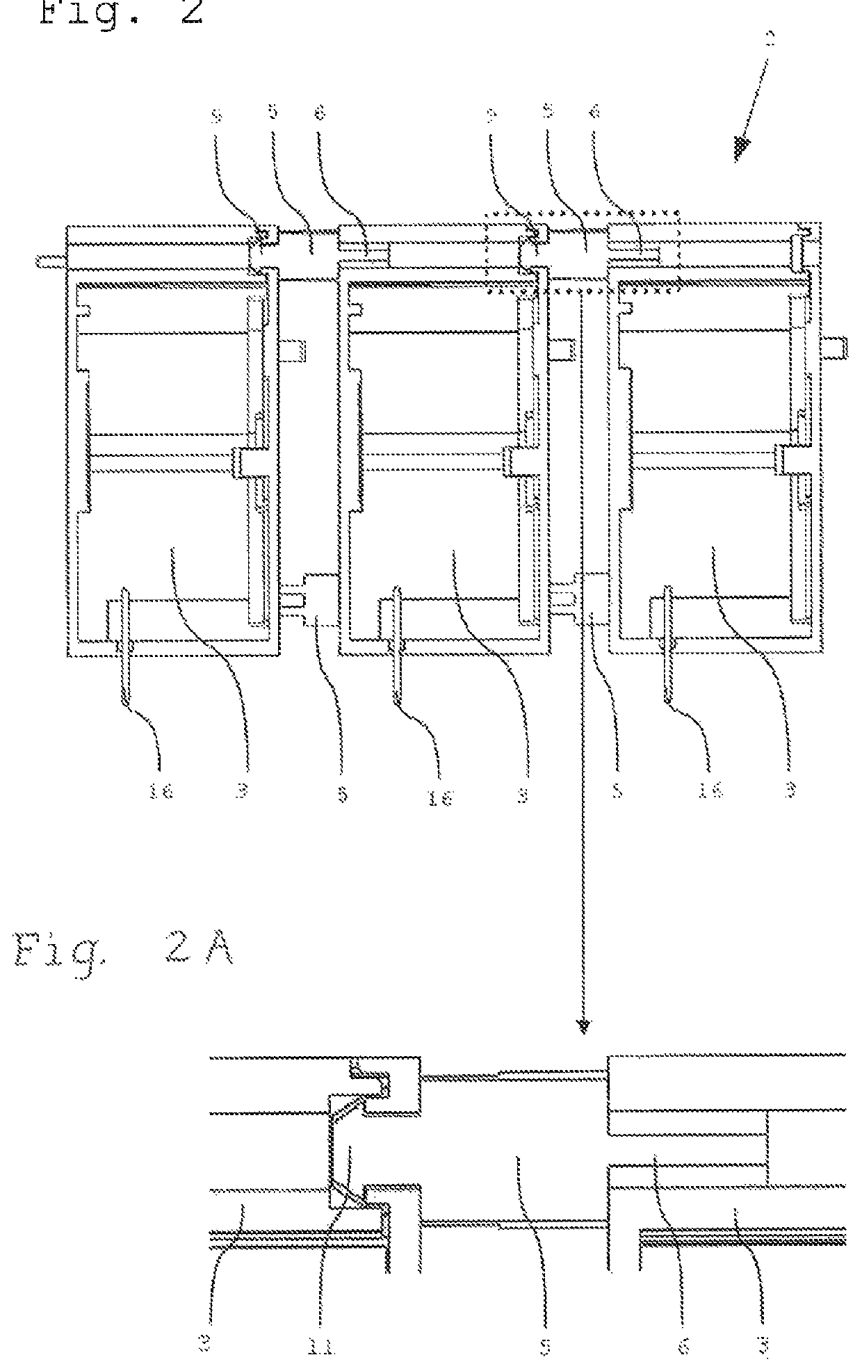
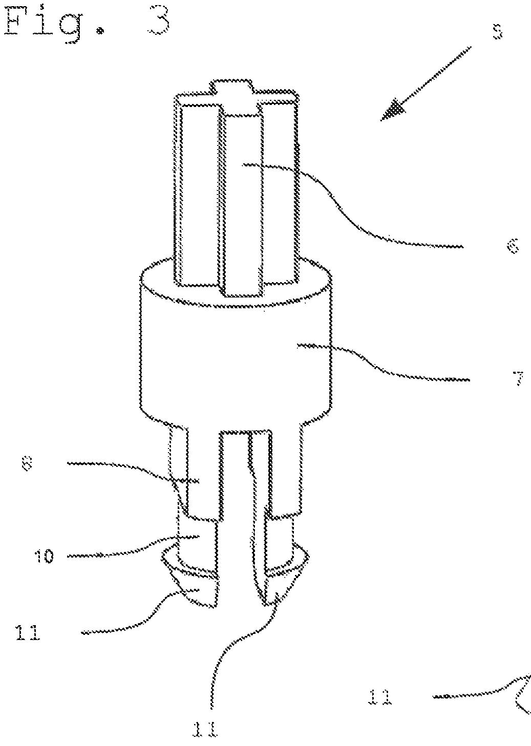
[0046]Embodiments of the invention shall be explained in more detail below with the aid of FIGS. 1 to 6.

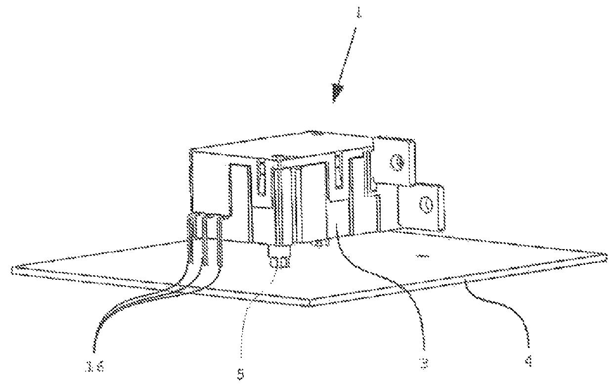
[0047]FIG. 1 illustrates a single relay 1 having a housing 3 and at least one dip solder pin 16. Relay 1 is fastened to an electrical board or circuit board 4 (hereinafter referred to as board) via two fastening clips 5 in accordance with an embodiment of the present invention. It is clear from FIG. 1 how the positioning of relay 1 on board 4 takes place with two fastening clips 5, wherein a defined distance between board 4 and relay housing 3 of single relay 1 is produced. As a result, it is easily possible to equip board 4 in this free space with other components, under the relay where necessary. Before the soldering of dip solder pins 16, relay 1 is reliably positioned and secured to board 4 against slipping or tilting in production. In addition, relay 1 is securely supported and potential forces acting during the connection of the relay are intercepted by fastening clips 5 and...


PUM


Abstract

A relay assembly comprises a relay mounted on a board. The relay may be a single or individual relay or a polyphasic relay. The relay has a housing and at least one dip solder pin extending from the housing and soldered to a circuit board. The relay is mounted on the circuit board via at least one fastening clip having a fitting part fitted into a hole in the housing, a latching part latched to a bore in the board, and a central flange between the fitting part and the latching part.

Description

CROSS REFERENCE TO RELATED APPLICATIONS[0001]This non-provisional patent application claims priority under 35 U.S.C. §119(a) from Patent Application No. 10 2013 101 736.3 filed in Germany on Feb. 21, 2013.FIELD OF THE INVENTION[0002]The invention relates to an arrangement for the fastening and positioning of relays, in particular both individual relays and polyphasic relays, together as well as directly on electrical boards or circuit boards which, for example, are used in electricity meters for switching currents in domestic, commercial and industrial appliances.BACKGROUND OF THE INVENTION[0003]A variety of technical solutions for the distancing and fastening of relays with generally rectangular housings are already known. A relay usually has a series of connections, known as dip solder pins, pointing in one direction, by means of which the components are soldered and interconnected to a circuit board. There are also solutions where the relay is plugged in simply by means of suitab...

Claims


Application Information

Patent Timeline
Patent Type & Authority Patents(United States)
IPC IPC(8): H01H45/04H05K3/30H01H50/14H01H50/04H01H9/26H01H1/58
CPCH01H45/04H01H50/047H01H50/14H05K3/301H01H1/5805H01H9/26H05K2201/10393H05K2201/10568H05K2201/2036
Inventor GASSMANN, JOERGHEINRICH, SOEREN
Owner JOHNSON ELECTRIC SA
Why Eureka
Try Eureka