Eureka AIR delivers breakthrough ideas for toughest innovation challenges, trusted by R&D personnel around the world.

Femoral cutting block

a cutting block and femoral technology, applied in the field of femoral cutting block and preparation of the distal femur, can solve the problems of increasing the cost of manufacture, high cost of such blocks, and affecting so as to improve the accuracy of anterior and posterior cuts, improve the accuracy of cutting, and improve the accuracy of distal cutting.

Inactive Publication Date: 2008-06-26
HOWMEDICA OSTEONICS CORP
View PDF41 Cites 0 Cited by
  • Summary
  • Abstract
  • Description
  • Claims
  • Application Information

AI Technical Summary

Benefits of technology

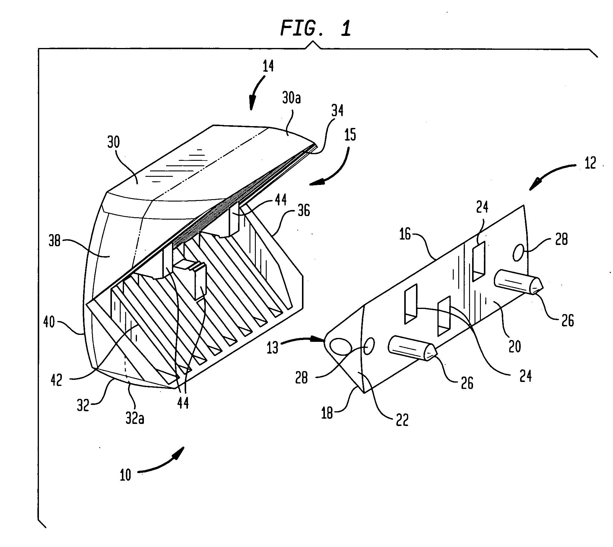
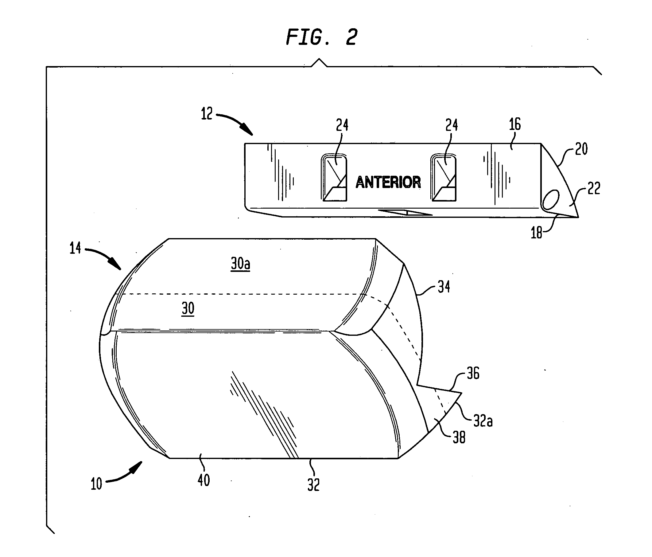
[0004]The present application provides a cutting block that may help overcome some of the above-mentioned disadvantages. The cutting block of the present application is a four-in-two (4-in-2) cutting block assembly which may improve the accuracy in the preparation of the distal femur for the implantation of a knee prosthesis. The cutting block assembly comprises a first block for making the anterior and posterior chamfer cuts and a second block for making the anterior and posterior cuts. The first and second blocks interlock which helps correlate the four cuts and improve the accuracy of the cuts. The second block includes extended cutting surfaces which may further help improve the accuracy of the anterior and posterior cuts. In addition, the second block provides a visual indication of the accuracy of the anterior and posterior chamfer cuts before the anterior and posterior cuts are made. Moreover, the cutting block can be made of polymeric material which may help reduce the cost of making the block. In addition, because polymeric material is relatively lightweight compared to metal, the cutting block may be relatively lightweight which may improve the handling of the cutting block during a surgical procedure.

Problems solved by technology

However, such conventional cutting blocks may exhibit various disadvantages.
In addition, these cutting blocks are made of metal which may increase the cost of manufacture.
Moreover, because of the high cost of such blocks, they are typically reused for additional surgical procedures.
However, this may require sterilization of the blocks which may be costly and inconvenient.

Method used


Image

  • Femoral cutting block
  • Femoral cutting block
  • Femoral cutting block

Examples


Embodiment Construction

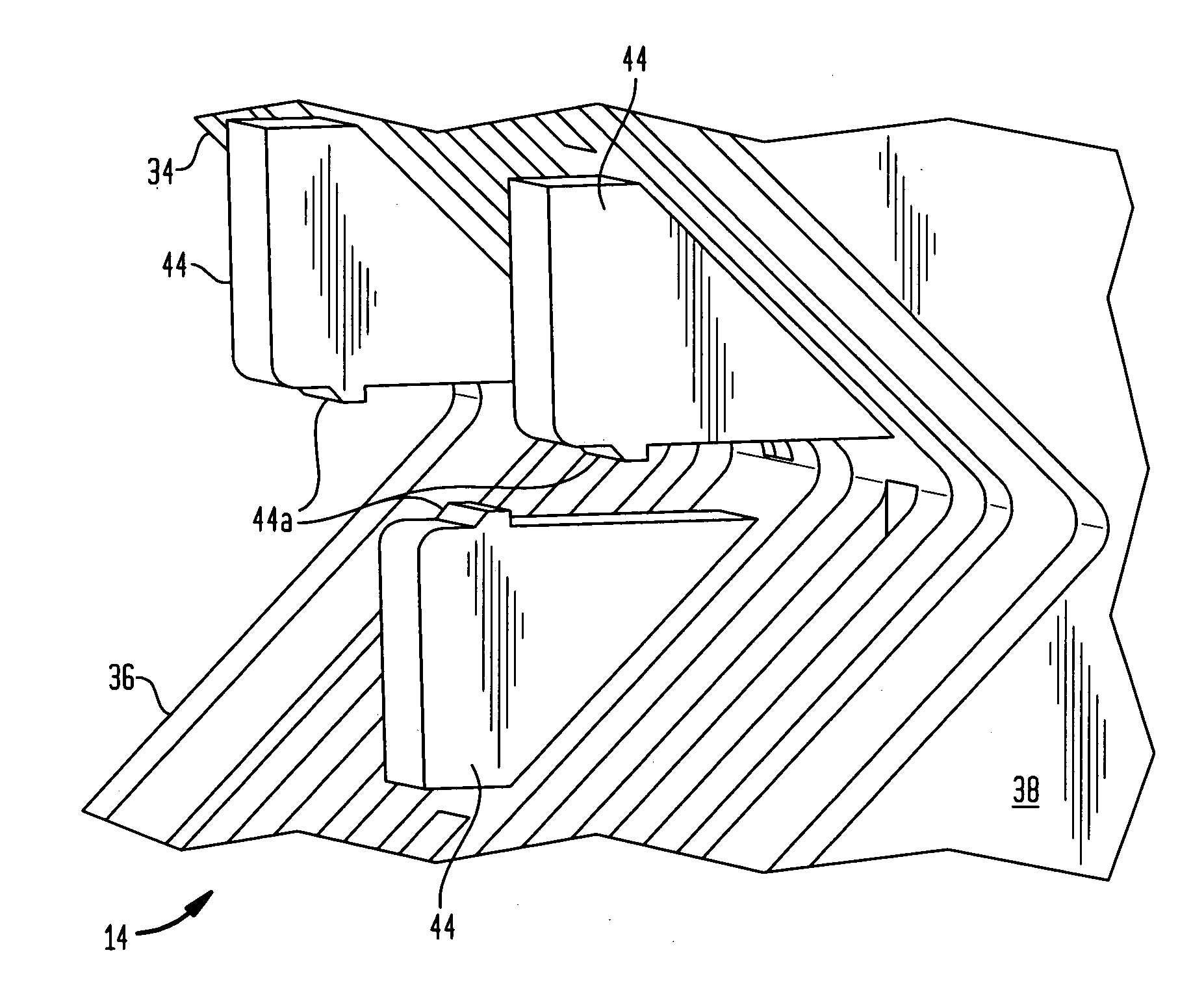
[0035]Referring to FIGS. 1-7, shown is a cutting block assembly generally denoted as 10 comprising a first block 12 capable of interlocking with a second block 14 to form a four-in-two (4-in-2) cutting block for resecting a portion of a bone such as a distal femur. Referring to FIGS. 1-2, the first block 12 is a generally triangular shaped block forming an anterior-chamfer cutting surface 16, a posterior-chamfer cutting surface 18, a contact surface 20 and side surfaces 22. The anterior-chamfer cutting surface 16 provides a guiding surface for making an anterior-chamfer cut on a femur (not shown). The posterior-chamfer cutting surface 18 provides a guiding surface for making a posterior-chamfer cut on the femur. The contact surface 20 includes protrusions 26 adapted to fit into holes in the distal femur to detachably couple the first block 12 to the distal resected surface of a distal femur (not shown), as explained below in further detail. In one embodiment, the protrusions 26 are ...


PUM


Abstract

A cutting block assembly comprising first and second interlocking blocks for resecting a distal femur. The first block has a first surface for providing a guiding surface for making an anterior chamfer cut on the femur and a'second surface for providing a guiding surface for making a posterior chamfer cut on the femur. The second block is adapted to detachably couple to the first block. The second block has a first surface for providing a guiding surface for making an anterior cut on the femur and a second surface for providing a guiding surface for making a posterior cut on the femur.

Description

BACKGROUND OF THE INVENTION[0001]The present application relates generally to the implant of prosthetic joints and pertains, more specifically, to the preparation of the distal femur for the implantation of a femoral knee prosthesis, utilizing a femoral cutting block to assist in establishing the surfaces necessary for locating and securing the prosthesis in place on the femur.[0002]The implant of a prosthetic knee joint requires that the distal femur be prepared to receive the femoral component of the knee prosthesis by cutting the bone of the femur to establish accurately located surfaces. Upon implantation, the femoral component will rest on these surfaces. As used herein, when referring to bones or other parts of the body, the term “proximal” means closer to the heart and the term “distal” means more distant from the heart. The term “inferior” means toward the feet and the term “superior” means towards the head. The term “anterior” means towards the front part of the body or the...

Claims


Application Information

Patent Timeline
Patent Type & Authority Applications(United States)
IPC IPC(8): A61B17/56
CPCA61B17/155
Inventor ROGER, CHRISTOPHER ABEE
Owner HOWMEDICA OSTEONICS CORP
Why Eureka
Eureka Blog
Learn More