Polyaxial bone screw with spherical capture, compression and alignment and retention structures

a technology of spherical capture and bone screw, applied in the field of polyaxial bone screw, can solve problems such as difficult or impossible to do, and achieve the effects of low profile, easy use and inexpensive production

Active Publication Date: 2008-06-26
NUVASIVE
View PDF4 Cites 186 Cited by
  • Summary
  • Abstract
  • Description
  • Claims
  • Application Information

AI Technical Summary

Benefits of technology

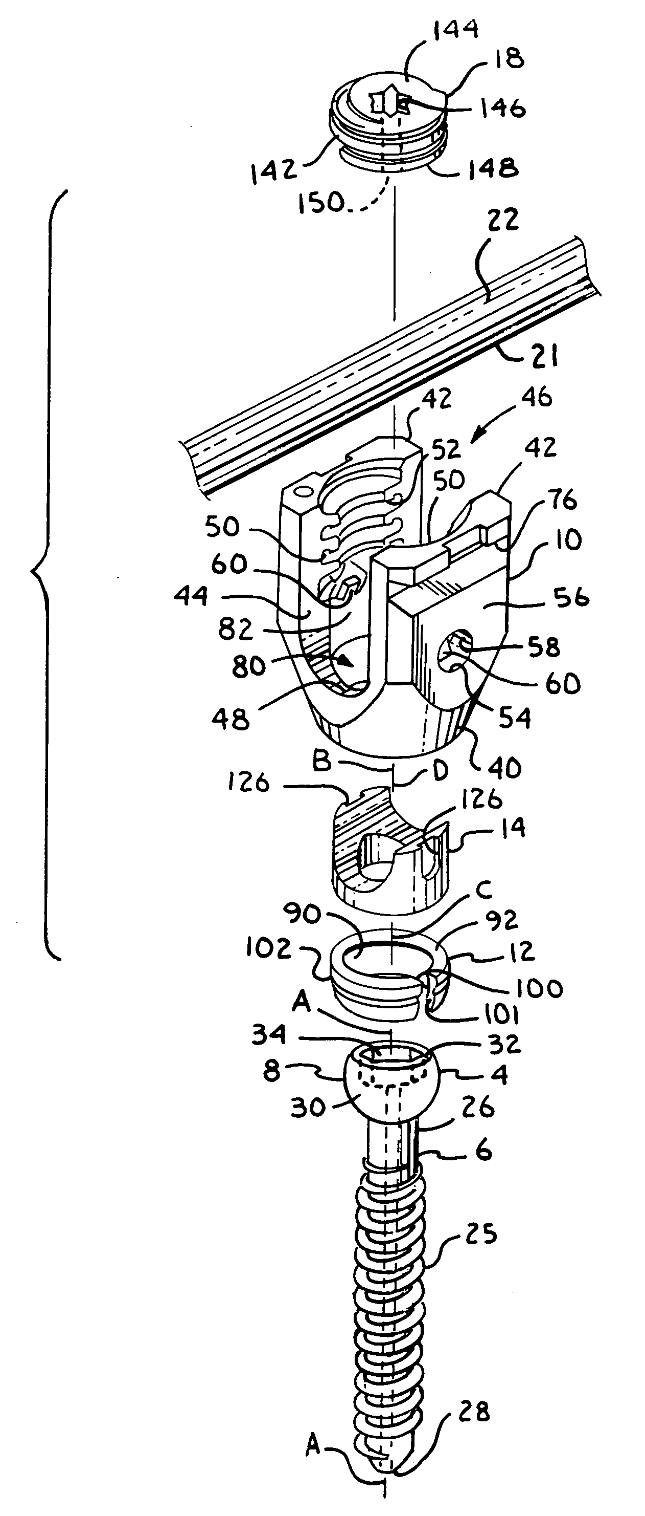
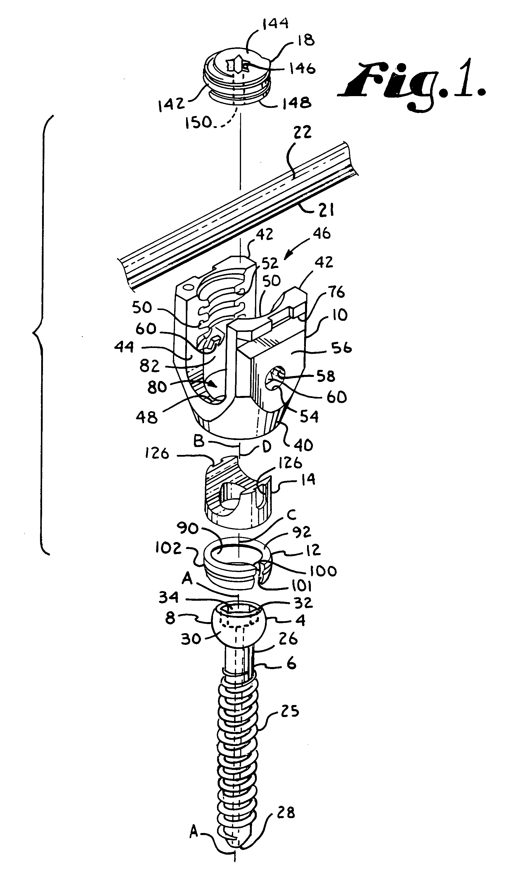
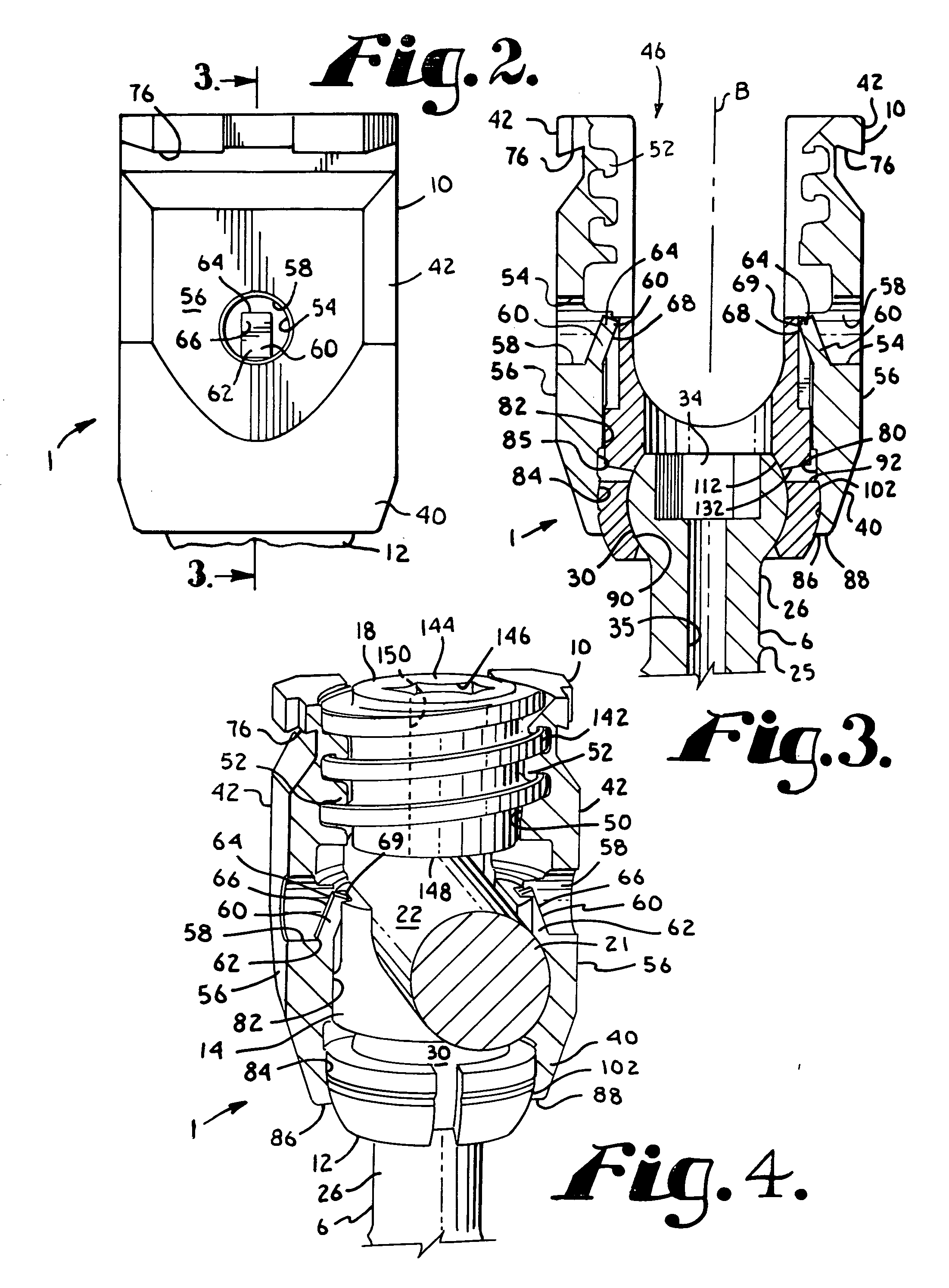
[0009]Therefore, objects of the present invention include: providing an improved spinal implant assembly for implantation into vertebrae of a patient; providing such an assembly that includes an open longitudinal connecting member receiver, a shank pivotally connected to the rod receiving member, a rod or other longitudinal connecting member, and in some instances, an aligned pressure insert disposed between the shank and the rod; providing such an assembly that has a low profile after final installation; and providing such an assembly that is easy to...

Problems solved by technology

This is sometimes very ...

Method used


Image

  • Polyaxial bone screw with spherical capture, compression and alignment and retention structures
  • Polyaxial bone screw with spherical capture, compression and alignment and retention structures
  • Polyaxial bone screw with spherical capture, compression and alignment and retention structures

Examples


third embodiment

[0073]With reference to FIGS. 15-21, a bone screw assembly of the invention, generally 301 includes a shank 304 that further includes a body 306 integral with an upper portion or capture structure 308; a head or receiver 310; a retainer 312 illustrated as an open collar-like retaining and articulating structure; and a compression insert 314. The shank 304, the receiver 310 and the retainer 312 are substantially similar to the respective shank 4, receiver 10 and retainer 12 previously described herein with respect to the assembly 1. The receiver 310 is sized and proportioned slightly differently than the receiver 12 to cooperate with the insert 314. However, the receiver 310 otherwise includes the same component parts previously described herein with respect to the receiver 10. In particular, the receiver 310 includes a central axis H, a base 340, arms 342, a U-shaped channel 344, an interior surface with a guide and advancement structure 352, a pair of opposed apertures 354 upwardly...

fourth embodiment

[0079]With reference to FIGS. 23 and 24, in a fourth embodiment according to the invention, generally 401, a receiver 410 is substantially identical to the receiver 310 of the assembly 301 with the exception that the spring tabs 360 are removed and replaced with a deformable material portion 460. The assembly 401 otherwise includes a shank 404, a retainer 412 and a compression insert 414 identical or substantially similar to the shank 304, retainer 312 and compression insert 314 previously described herein with respect to the assembly 301. Formed on outside surfaces 456 of the receiver 410 are a pair of opposed apertures 457. Each deformable portion or wall 460 partially defines the respective aperture 457. A tool (not shown) is inserted into the aperture and is pressed against the deformable portion 460, causing the portion 460 to extend into a cavity 480 of the receiver 410 in a direction towards a central axis J. Similar to the spring tabs 360, the now deformed wall portions 460 ...


PUM


Abstract

A polyaxial bone screw assembly includes a receiver, a shank, an articulation structure for retaining the shank in the receiver and a compression insert for engagement with a longitudinal connecting member such as a rod. The articulation structure includes substantially spherical convex and concave surfaces that slidably engage both shank and receiver surfaces to provide compound articulation between the receiver and the shank. The receiver includes inwardly directed spring tabs engaging the insert and prohibiting rotation of the insert within the receiver.

Description

CROSS REFERENCE TO RELATED APPLICATIONS[0001]This application claims the benefit of U.S. Provisional Application No. 60 / 905,472 filed Mar. 7, 2007, which is incorporated by reference herein. This application is also a continuation-in-part of U.S. patent application Ser. No. 11 / 126,965 filed May 10, 2005 which is incorporated by reference herein. This application is also a continuation-in-part of U.S. patent application Ser. No. 12 / 008,067 filed Jan. 8, 2008 that claims the benefit of U.S. Provisional Application No. 60 / 897,723 filed Jan. 26, 2007, both of which are incorporated by reference herein.BACKGROUND OF THE INVENTION[0002]The present invention is directed to polyaxial bone screws for use in bone surgery, particularly spinal surgery, and particularly to capture structures and inserts for such screws.[0003]Bone screws are utilized in many types of spinal surgery in order to secure various implants to vertebrae along the spinal column for the purpose of stabilizing and / or adjus...

Claims


Application Information

Patent Timeline
IPC IPC(8): A61B17/56
CPCA61B17/7037A61B17/7032A61B17/7035
Inventor JACKSON
Owner NUVASIVE
Why Eureka
Try Eureka