

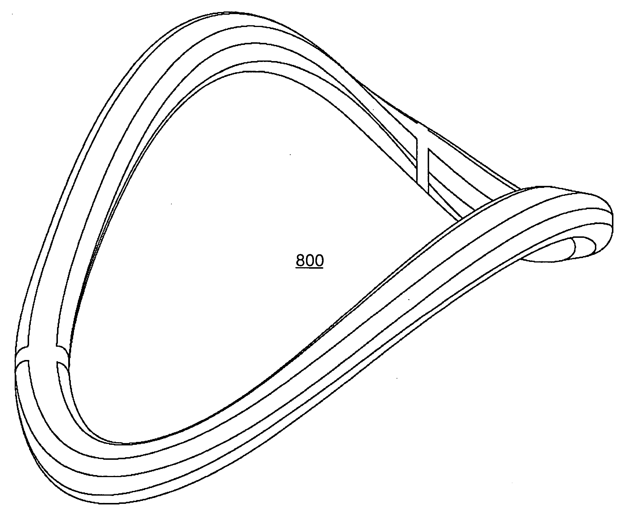
Non-planar cardiac vascular support prosthesis
a vascular support and non-planar technology, applied in the field of non-planar cardiac vascular support prosthesis, can solve the problems of insufficient valvular function, less durable repairs without rings, and difficulty in designing flexible rings
- Summary
- Abstract
- Description
- Claims
- Application Information
AI Technical Summary
Problems solved by technology
Method used
Image

Examples
Embodiment Construction
[0018]Reference will now be made in detail to the present invention, examples of which are illustrated in the accompanying drawings, wherein like reference numerals refer to like elements throughout.
[0019]Studies have shown that complex mitral valve suffer durability problems. That is, repairs requiring chordal transfer / shortening and leaflet suture lines. In many cases these long-term failures are the result of disruption at leaflet, chordal or annular suture lines. Frank chordal rupture also leads to recurrent mitral regurgitation. Such failure mechanisms suggest stress and the resulting strain as an etiologic factor.
[0020]Leaflet, chordal and annular stress are directly proportional to load (the difference between systolic LV and left atrial pressure) and leaflet area and inversely proportional to leaflet curvature (Laplace's law). Mitral leaflet curvature is in turn governed by two mechanisms. The most obvious and well described is leaflet billowing. The leaflet area of the huma...
PUM
 Abstract
Description
Claims
Application Information