Foldable Mast Assembly for a Sailing Vessel

a sailing vessel and mast technology, applied in the field of sailing vessel mast assembly, can solve the problems of limiting the use or transportability of watercraft, limiting the ability of sailing vessels to pass under low lying structures, and difficult transportation of sailing vessels, so as to achieve easy folding and reduce discontinuities

Inactive Publication Date: 2008-07-03
SUSQUEHANNA YACHT MFG
View PDF24 Cites 24 Cited by
  • Summary
  • Abstract
  • Description
  • Claims
  • Application Information

AI Technical Summary

Benefits of technology

[0006]To address at least some of the above issues, the inventors have provided, as one example, a foldable mast assembly for a sailing vessel, comprising: a lower mast section; an intermediate mast section having a lower end foldably coupled to an upper end of the lower mast section; an upper mast section having a lower end foldably coupled to an upper end of the intermediate mast section; and a boom coupled to the lower mast section. By coupling the boom to the lower section of the mast assembly, the inventors have recognized that the intermediate and upper mast sections may be more easily folded, without necessarily requiring reconfiguration of the boom.
[0007]As another example, the inventors have provided a foldable mast assembly for a sailing vessel, comprising: an upper mast section including a first track segment at a stern side of the upper mast section, the first track segment being adapted to guide a luff edge of a sail between a raised configuration and a lowered configuration of the sail; an intermediate mast section including a second track segment at a stern side of the intermediate mast section, the second track segment being adapted to guide the luff edge of the sail between the raised configuration and lowered configuration; a first hinge assembly foldably coupling a lower end of the upper mast section at a bow side of the upper mast section to an upper end of the intermediate mast section at a bow side of the intermediate mast section. Thus, the inventors have recognized that in some examples, placing the hinge on an opposite of the mast assembly from the track can reduce discontinuities between two track sections that are located at different foldable mast sections.
[0008]As yet another example, the inventors have provided a foldable mast assembly for a sailing vessel providing at least an erected position and a folded position, comprising: a lower mast section; a stepping support fixedly coupling the lower mast section to a sailing vessel; an intermediate mast section having a lower end rotationally coupled to an upper end the lower mast section by a first hinge assembly that permits an upper end of the intermediate mast section to rotate from the erected position toward the stern of the sailing vessel and into the folded position without unstepping the lower mast section from the stepping support; and an upper mast section having a lower end rotationally coupled to an upper end of the intermediate mast section by a second hinge assembly that permits an upper end of the upper mast section to rotate from the erected position toward the bow of the sailing vessel and into the folded position without unstepping the lower mast section from the stepping support. In this way, the mast assembly can be folded or erected without requiring the mast assembly to be unstepped from the stepping support.

Problems solved by technology

In some examples, the size and / or configuration of the mast can impose limitations on the use or transportability of the watercraft.
However, where the mast is of greater length than the hull, the mast may extend considerably beyond the hull profile, thereby making transportation of the sailing vessel more difficult.
Furthermore, during operation of the sailing vessel, the height of the mast may also limit the ability of the sailing vessel to pass under low lying structures, such as bridges or wires that are located at a relatively low height above the water.
The process of stepping and unstepping the mast can also be difficult, work intensive, and time consuming.
For example, some masts may require the assistance of multiple people to complete the stepping process due to the size and / or weight of the mast.
Further still, mast stays or guy wires may be adjusted, reattached, or disassembled as a consequence of the stepping or unstepping process, thereby further complicating the stepping process.
However, the inventors have recognized some issues with the above approach.
As one example, the inventors have recognized that the approach of Lewis does not address how a boom structure may be treated during the mast stepping and unstepping process.
Furthermore, the inventors have recognized that the approach of Lewis hinges two mast sections on the sail, which can reduce the continuity of the track across a joint or interface between two mast sections or obstruct the track.
Further still, the approach by Lewis still requires stepping and unstepping of the mast for purposes of transportation and storage.

Method used


Image

  • Foldable Mast Assembly for a Sailing Vessel
  • Foldable Mast Assembly for a Sailing Vessel
  • Foldable Mast Assembly for a Sailing Vessel

Examples


Embodiment Construction

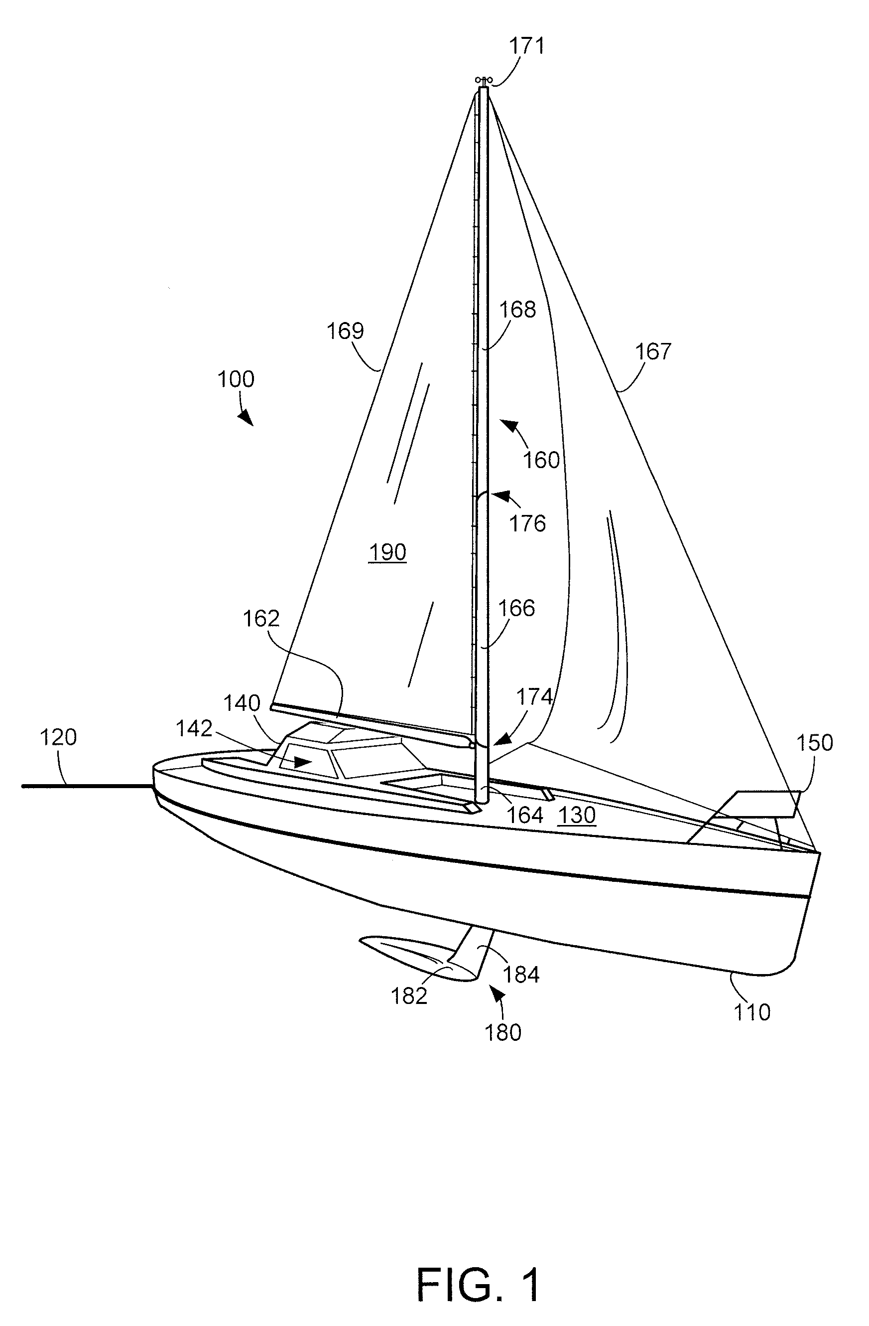
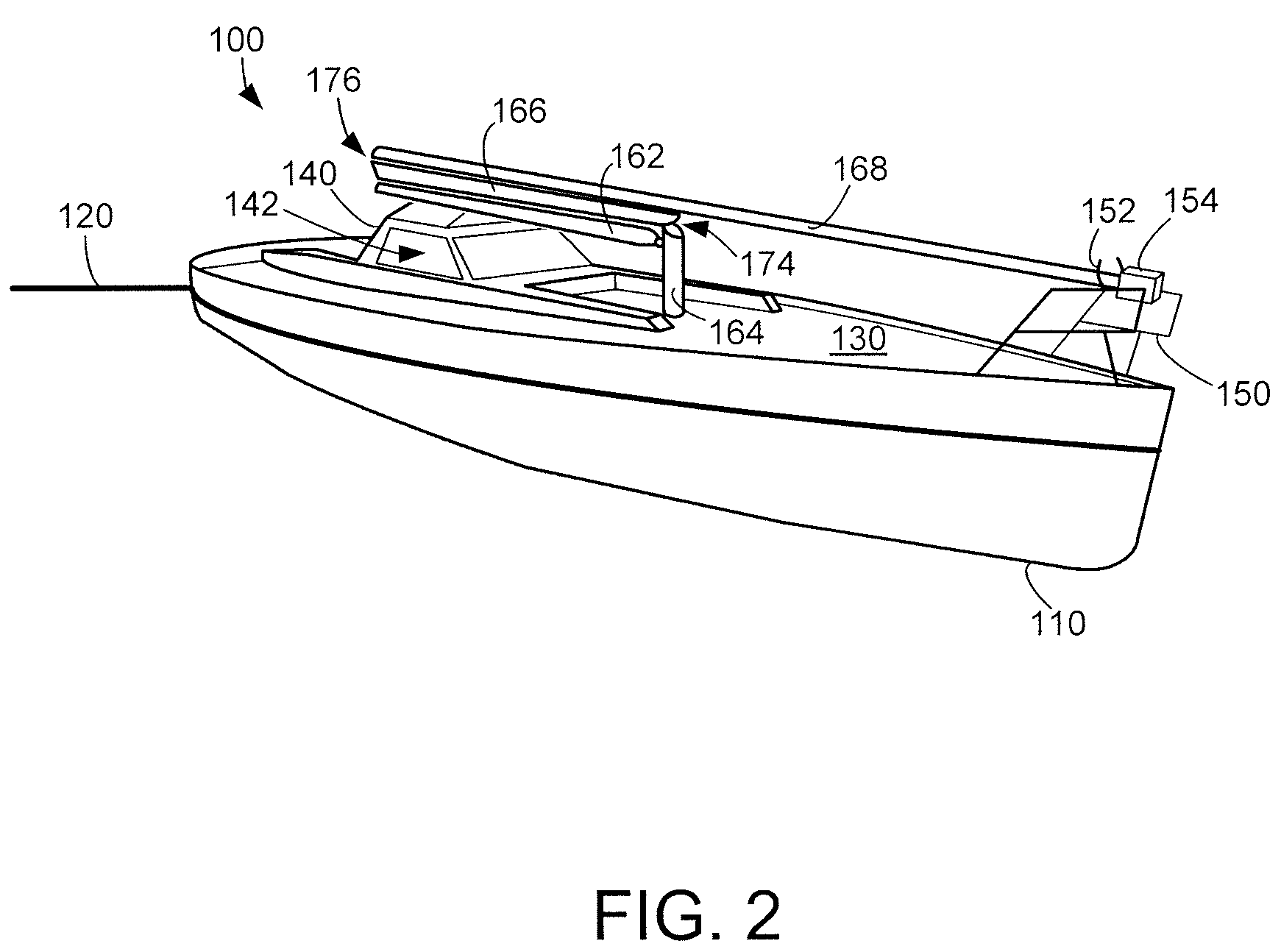
[0030]Referring to FIG. 1, an example watercraft having a sailboat configuration is provided. In particular, FIG. 1 illustrates a watercraft 100 including a hull 110 which is at least partially submerged beneath water line 120. As illustrated in FIG. 1, hull 110 may be configured as a displacement hull, at least during some conditions. Hull 110 may include a deck 130, which may at least partially support a bridge 140, a cockpit area 142, a pulpit 150, and a mast assembly 160.

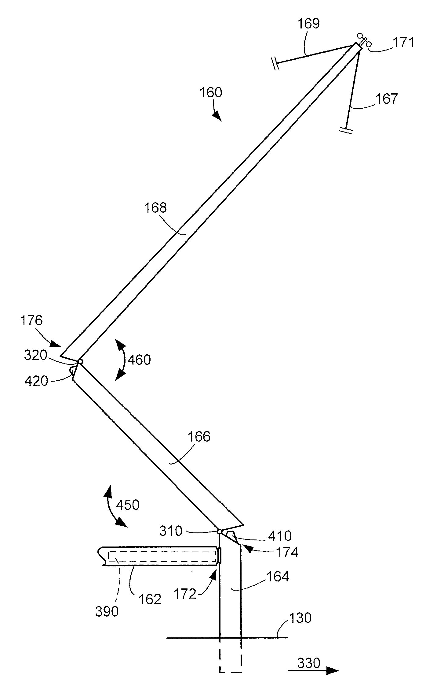
[0031]Mast assembly 160 may include a boom 162 and / or other suitable structure for supporting one of more sails. Mast assembly 160 including boom 162 is shown in FIG. 1 supporting a sail 190. Boom 162 may include a furling system, whereby sail 190 can be at least partially stored within the boom structure, for example, by rolling within an internal region of the boom. Boom 162 may be coupled to mast assembly 160 at lower mast section 164.

[0032]Mast assembly 160 may also include one or more sensors indicated gene...


PUM


Abstract

As one non-limiting example, a foldable mast assembly for a sailing vessel is provided. The foldable mast assembly includes a lower mast section; an intermediate mast section having a lower end foldably coupled to an upper end of the lower mast section; an upper mast section having a lower end foldably coupled to an upper end of the intermediate mast section; and a boom coupled to the lower mast section. A locking device internal the mast assembly is also provided to inhibit folding of the mast assembly.

Description

[0001]The present application claims priority to U.S. Provisional Patent Application No. 60 / 883,321, filed Jan. 3, 2007, and entitled “Reconfigurable Watercraft”, the entire contents of which are incorporated herein by reference.BACKGROUND AND SUMMARY[0002]Sailing vessels can utilize a mast for supporting one or more sails. In some examples, the size and / or configuration of the mast can impose limitations on the use or transportability of the watercraft. As one example, a sailing vessel may be transported by trailer between two bodies of water or between a body of water and a storage location. During transportation, the mast may be removed or unstepped from the deck or hull where it may be secured along the length of the hull to reduce the height of the sailing vessel. However, where the mast is of greater length than the hull, the mast may extend considerably beyond the hull profile, thereby making transportation of the sailing vessel more difficult. Furthermore, during operation o...

Claims


Application Information

Patent Timeline
Patent Type & Authority Applications(United States)
IPC IPC(8): B63B15/00
CPCB63B2015/0066B63B15/0083
Inventor KNISELY, CHARLES W.BAYLOR, HENRY M.O'ROURKE, MATTHEW A.WALKER, THOMAS C.CLARK, JACOB C.D.
Owner SUSQUEHANNA YACHT MFG
Why Eureka
Try Eureka