Flat panel display mounting system

a technology for mounting systems and flat panels, applied in the field of television displays, can solve the problems of many of the mounting systems that are available that are not versatile, and achieve the effect of preventing disassembly

Inactive Publication Date: 2008-07-03
TWIN STAR INT
View PDF26 Cites 64 Cited by
  • Summary
  • Abstract
  • Description
  • Claims
  • Application Information

AI Technical Summary

Benefits of technology

[0016]In another preferred embodiment of the present invention, a television mounting system includes a wall plate having an upper end and a lower end, a locking bar pivotally mounted to the wall plate, the locking bar being movable between a locked position and an unlocked position, and at least one monitor arm mountable on the wall plate, whereby in the locked position the locking bar prevents dismounting of the at least one monitor arm from the wall plate. The at least one monitor arm desirably includes a tilt adjustment mechanism for selectively adjusting the tilt of the at least one monitor arm relative to the wall plate. The wall plate may include a first wall plate section, a second wall plate section and an expansion plate that couples the first and second wall plate sections together, whereby the first and second wall plate sections are movable away from one another for expanding the size of the wall plate.
[0018]In one or more preferred embodiments, the at least one monitor arm includes a first hook, a second hook spaced from the first hook and a C-shaped opening underlying the second hook, whereby the locking bar engages the C-shaped opening underlying the second hook when the locking bar is in the locked position for preventing dismounting of the at least one monitor arm from the wall plate.

Problems solved by technology

Many of the mounting systems that are available are not versatile.

Method used


Image

  • Flat panel display mounting system
  • Flat panel display mounting system
  • Flat panel display mounting system

Examples


Embodiment Construction

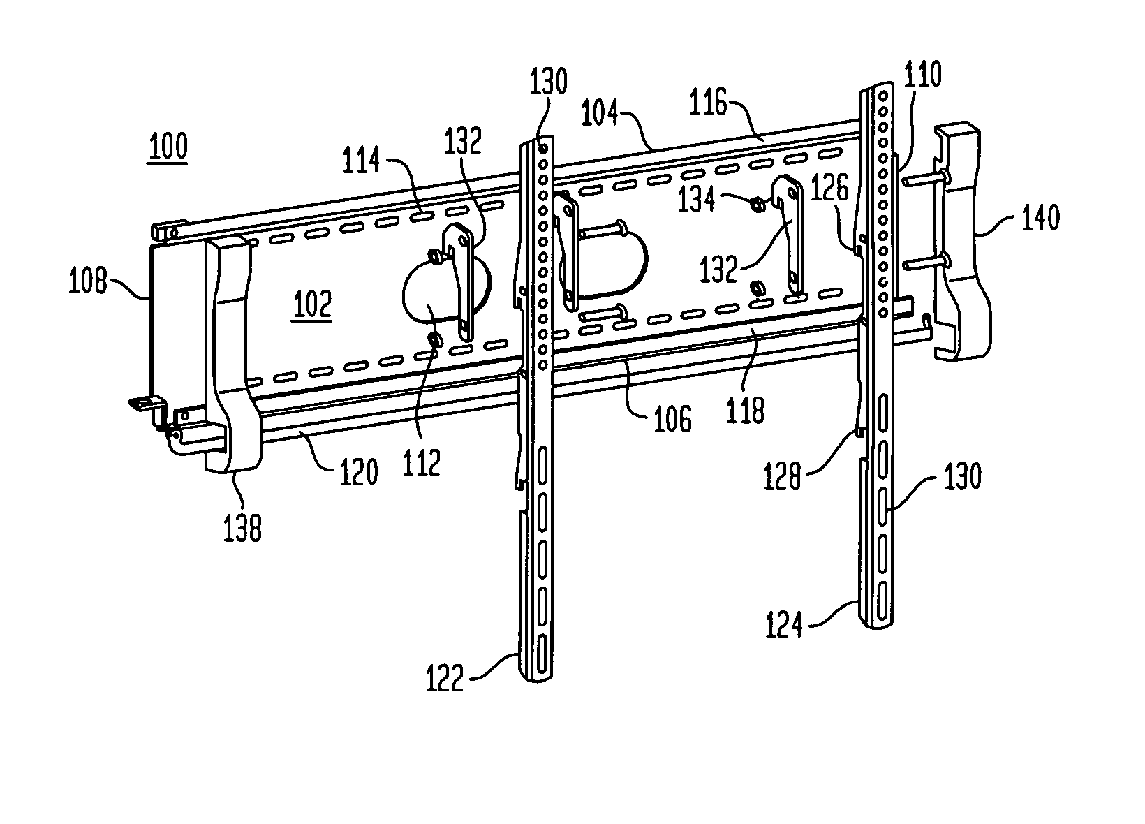
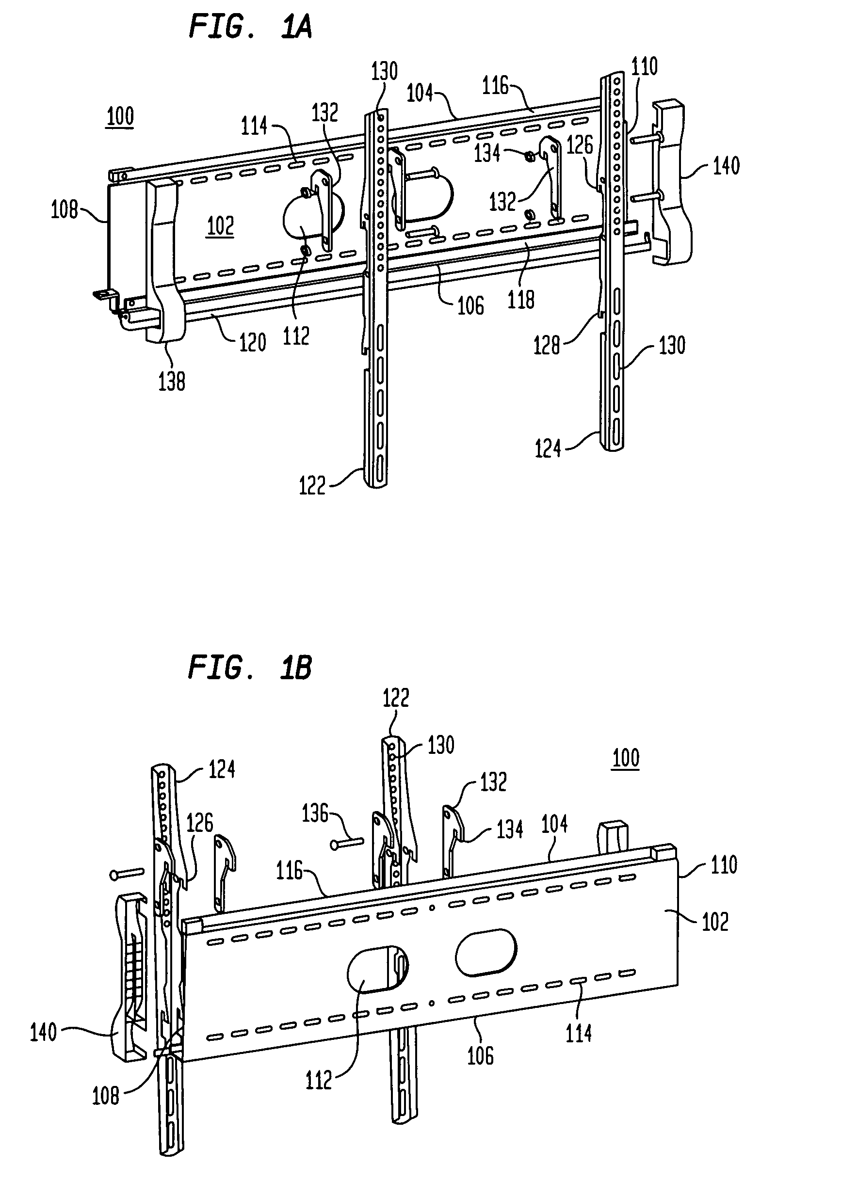
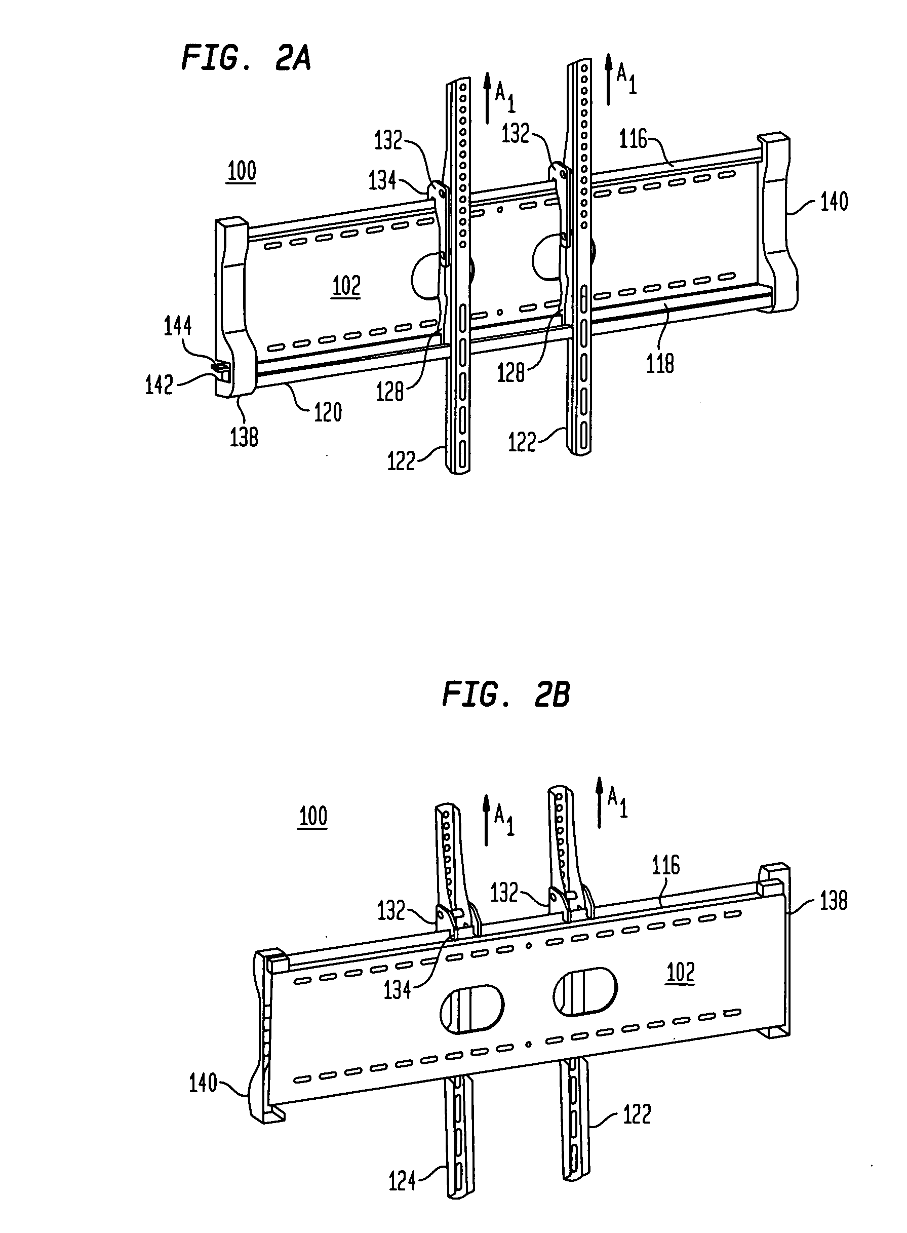
[0049]Referring to FIGS. 1A and 1B, in certain preferred embodiments of the present invention, a television mounting system 100 includes a wall plate 102 having an upper end 104, a lower end 106, a first side 108 and a second side 110. The wall plate 102 is preferably made of a sturdy material such as metal. The wall plate has one or more central openings 112 extending from a first face to the second face thereof. The openings 112 are preferably used for passing wires or cables through the wall plate 102, such as audio, video or power cables. The cables passed through the central openings 112 are preferably connected with a television monitor for supplying power, audio or video to the television monitor. The wall plate also includes a plurality of mounting openings 114 used for securing the wall plate 102 to a wall.

[0050]Wall plate 102 includes a top ledge 116 that extends along the upper end 104 of the wall plate. The top ledge 116 preferably extends between the first and second si...


PUM


Abstract

A television mounting system includes a wall plate, at least one monitor arm mountable on the wall plate, and a locking element permanently connected with the wall plate and being movable between an unlocked position for enabling dismounting of the at least one monitor arm from the wall plate and a locked position for preventing dismounting of the at least one monitor arm from the wall plate. The locking element may be pivotally attached to the wall plate for pivoting between the unlocked and locked positions. The at least one monitor arm cannot be removed from the wall plate when the locking element is in the locked position.

Description

BACKGROUND OF THE INVENTION[0001]The present invention relates to television displays and more particularly relates to television mounting systems for flat panel displays.[0002]Recently, there has been a marked growth in the popularity of flat panel displays, and in particular flat panel televisions. Flat panel televisions presently use one of two technologies, either liquid crystal or plasma display, to provide a display screen that is much thinner and lighter than traditions cathode ray televisions or projection televisions. Flat panel televisions are also versatile and that they can be placed on a stand or mounted on numerous surfaces such as a wall.[0003]The variety and accessibility of flat panel televisions is increasing as more manufacturers enter the market and larger flat panel televisions are produced. Presently, each manufacturer of flat panel televisions offer mounting brackets, stands or other hardware that is uniquely designed to mount that particular brand of flat pan...

Claims


Application Information

Patent Timeline
Patent Type & Authority Applications(United States)
IPC IPC(8): E04G3/00F16M11/00E04G5/06
CPCF16M13/02F16M11/10
Inventor SCULLER, STEVEN J.ZAMBELLI, MICHAEL P.AN, JIMMYJANG, IN-YOUNG
Owner TWIN STAR INT
Why Eureka
Try Eureka