Low-Pass Step Attenuator

a step attenuator and low-pass technology, applied in waveguide type devices, two-way working systems, television systems, etc., can solve the problems of inconvenient use, disadvantages of high-pass filters, and inability to provide uniform attenuation for a range of frequencies, and achieve the effect of higher uniform attenuation

Inactive Publication Date: 2008-07-03
PPC BROADBAND INC
View PDF7 Cites 48 Cited by
  • Summary
  • Abstract
  • Description
  • Claims
  • Application Information

AI Technical Summary

Benefits of technology

[0007]The present invention addresses the above needs and achieves other advantages by providing a circuit that produces a frequency response having a low-pass portion with relatively little or no attenuation, a high-pass portion with relatively little or no attenuation, and a flat loss portion with relatively higher uniform attenuation.

Problems solved by technology

A high-pass filter is disadvantageous because outside of a transition range it provides either very large attenuation or no attenuation at all to a signal at a particular frequency.
A high-pass filter also cannot provide uniform attenuation across a range of frequencies.
A conventional step attenuator, however, is not suitable for the situation in which two sources of return path signals requiring different levels of attenuation are present.
Yet a windowed filter suffers from at least the same difficulties as the full band step attenuator discussed above.
The passband cannot apply different levels of uniform attenuation to different sources of return path signals, and the regions of the spectrum outside of the high-pass region and the passband region are of non-uniform attenuation.

Method used


Image

  • Low-Pass Step Attenuator
  • Low-Pass Step Attenuator
  • Low-Pass Step Attenuator

Examples


Embodiment Construction

[0020]The present invention now will be described more fully hereinafter with reference to the accompanying drawings, in which some, but not all embodiments of the inventions are shown. Indeed, these inventions may be embodied in many different forms and should not be construed as limited to the embodiments set forth herein; rather, these embodiments are provided so that this disclosure will satisfy applicable legal requirements. Like numbers refer to like elements throughout.

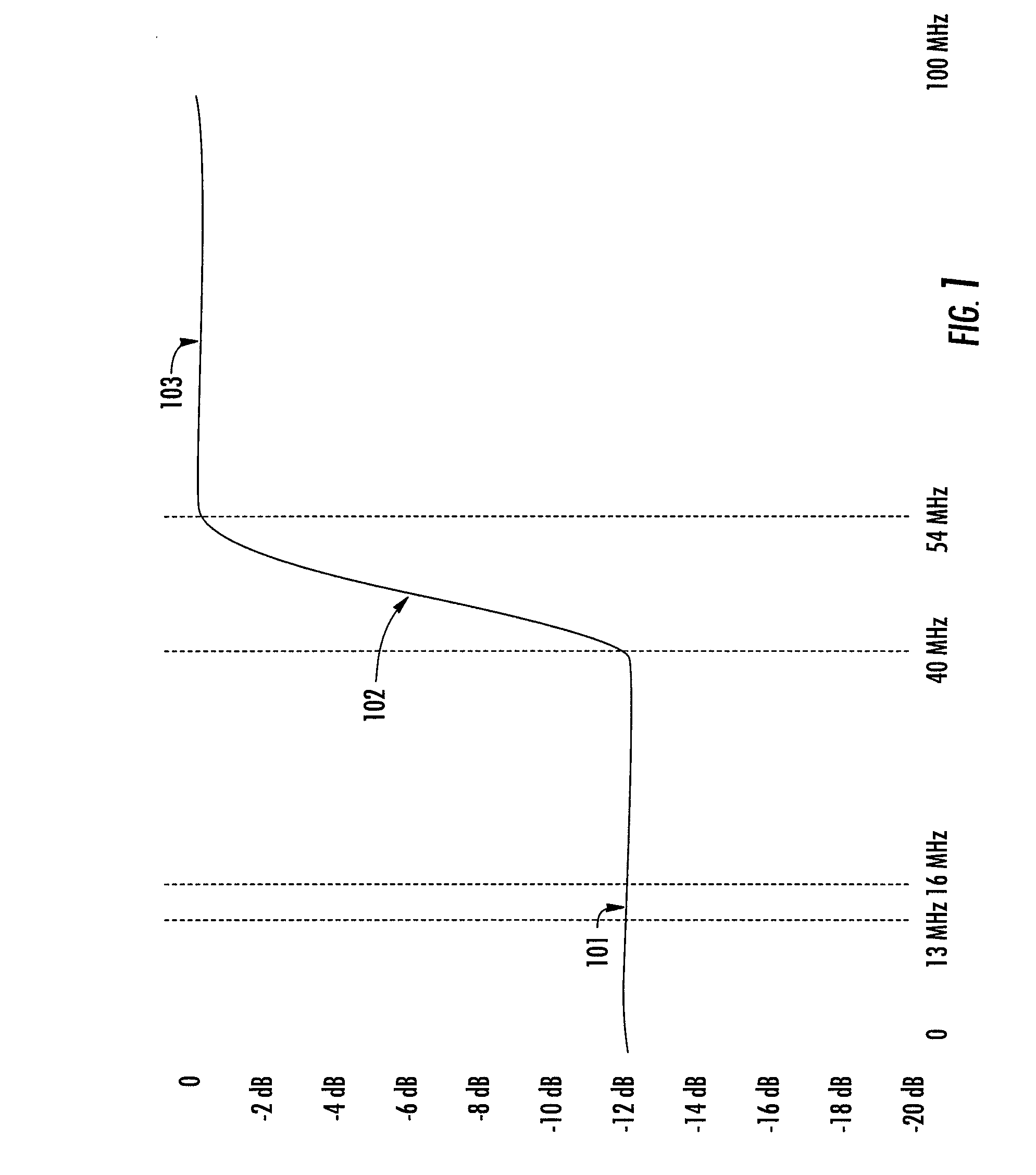
[0021]With reference to the drawings, in FIG. 1 there is shown a plot of insertion loss as a function of frequency in a prior art step attenuator. The vertical axis represents insertion loss in dB. The horizontal axis represents bandwidth from DC to 100 MHz. An attenuating portion of the bandwidth 101 shows flat attenuation of approximately 12 dB from DC to 40 MHz. A transition portion 102 exists from 40 MHz to 54 MHz. There is no attenuation in the high-pass portion 103 above 54 MHz.

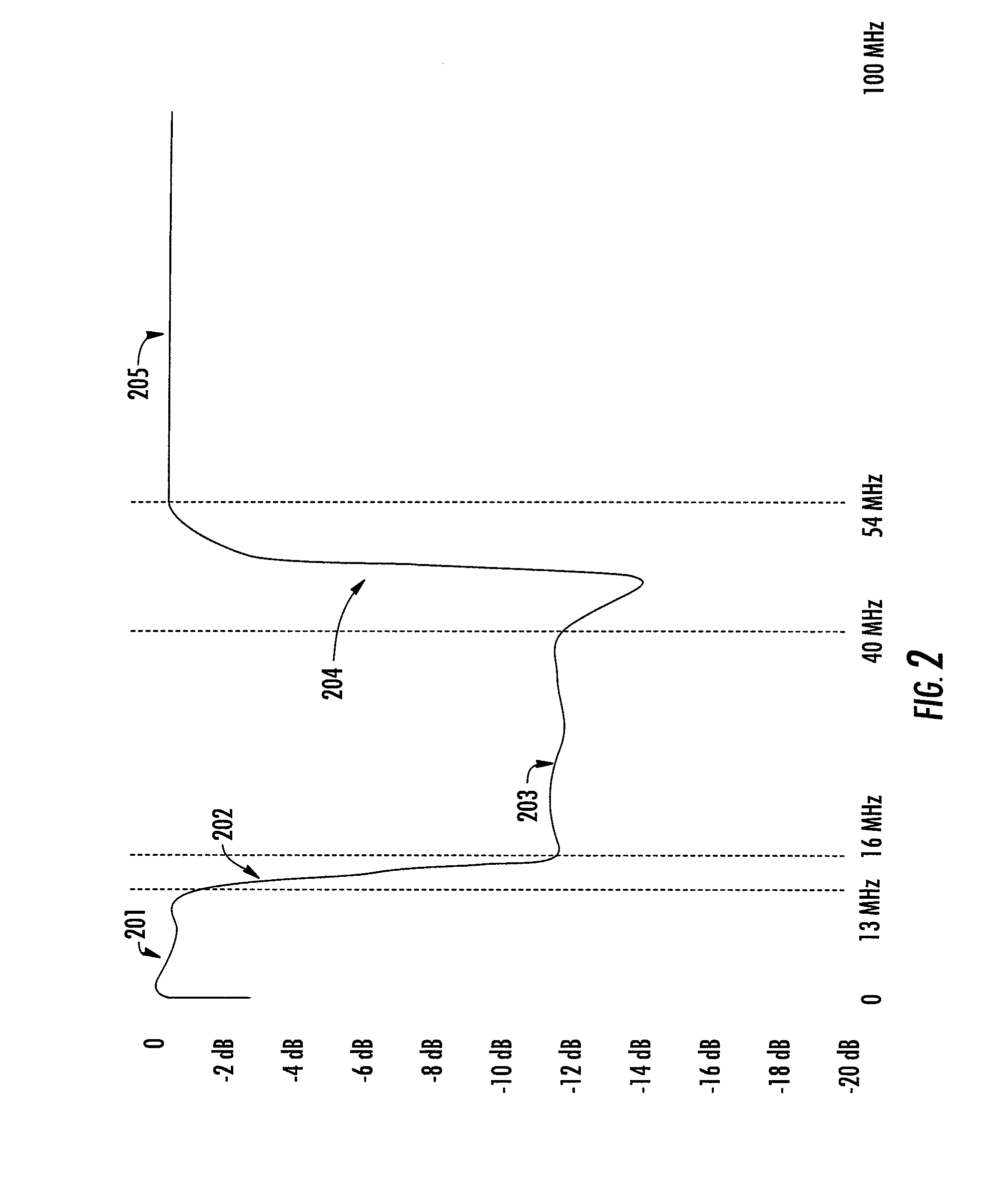
[0022]FIG. 2 depicts a plot...


PUM


Abstract

A filter circuit is constructed as a triplex filter having a high-pass filter, a low-pass filter with attenuation in the passband, and a second low-pass filter without attenuation in the passband. The filter circuit has a frequency response with a high-pass portion, a flat loss portion, and a low-pass portion. Attenuation in the flat loss portion is uniform and is predetermined via selection of filter components. The filter circuit is useful in a bidirectional CATV system in which performance is improved by selectable attenuation of a first source of return path signals but without attenuation of a second source of return path signals.

Description

BACKGROUND OF THE INVENTION[0001]Many communications systems allocate separate frequency bands for signals from different sources. One such example is a bidirectional cable (“CATV”) system with a forward path from a head end to one or more subscribers and a return path from the subscribers to the head end. Signals on the forward path may include broadcast television channels. Signals on the return path may include data from a subscriber's cable modem. It is common for signals on the forward path of a CATV system to be transmitted in one frequency band and for signals on the return path to be transmitted in a second frequency band which is lower than and does not overlap with the first frequency band.[0002]CATV systems are commonly designed to provide proper signal levels on the forward path at each subscriber tap. In a bidirectional CATV system, insertion loss in the return path may differ widely among taps. Performance of bidirectional systems can be significantly improved by appro...

Claims


Application Information

Patent Timeline
Patent Type & Authority Applications(United States)
IPC IPC(8): H03H7/01
CPCH03H7/0115H03H7/06H03H7/075H03H2250/00H03H7/1766H03H7/24H03H7/1758
Inventor PALINKAS, RAYOLCEN, AHMET BURAKHART, TOM
Owner PPC BROADBAND INC
Why Eureka
Try Eureka