RFID inventory device

a technology of inventory device and inventory device, which is applied in the direction of burglar alarm by hand-portable article removal, burglar alarm mechanical actuation, instruments, etc., can solve the problems of limited ability to physically tag individual items, difficult or impossible tagging, and limited ability to tag individual items

Inactive Publication Date: 2008-07-03
IBM CORP
View PDF8 Cites 66 Cited by
  • Summary
  • Abstract
  • Description
  • Claims
  • Application Information

AI Technical Summary

Benefits of technology

[0005]The present invention provides for automating the inventorying and tracking of small items by tagging the container in which they are placed with an radio frequency identification (RFID) inventory device that identifies the current number of items stored in the container. The RFID inventory device incorporates one or more sensors to detect the addition

Problems solved by technology

However, the ability to tag individual items can be limited in some circumstances.
First, the ability to physically tag individual items can be limited.
Although relatively large items can be easily tagged using RFID technology, the physical space on smaller items is often limited, making tagging difficult or impossible.
However, even if tagging is possible, tagging may be undesirable, as it can affect the usage of the item.
For example, some medical instruments and pharmaceutical products are often small, affording no space for an RFID tag.
Additionally, because of sterility or purity requirements, it is not desirable to introduce any foreign substances or sources contaminants, such as RFID ink, onto these types of objects.
Second, cost is an issue for tagging smaller items.
For an item with high production costs, the additional costs associated with incorporating an RF tag are often inconsequential.
However, for many smaller items, the cost of the RF tag can often exceed the cost of producing t

Method used


Image

  • RFID inventory device
  • RFID inventory device
  • RFID inventory device

Examples


Embodiment Construction

[0022]With reference now to the various figures in which like elements are identically numbered throughout, a description of the various embodiments of the present invention will now be provided. While the invention is disclosed in the context of a single arrangement, it can be appreciated that the invention can include numerous modifications from the presented embodiment.

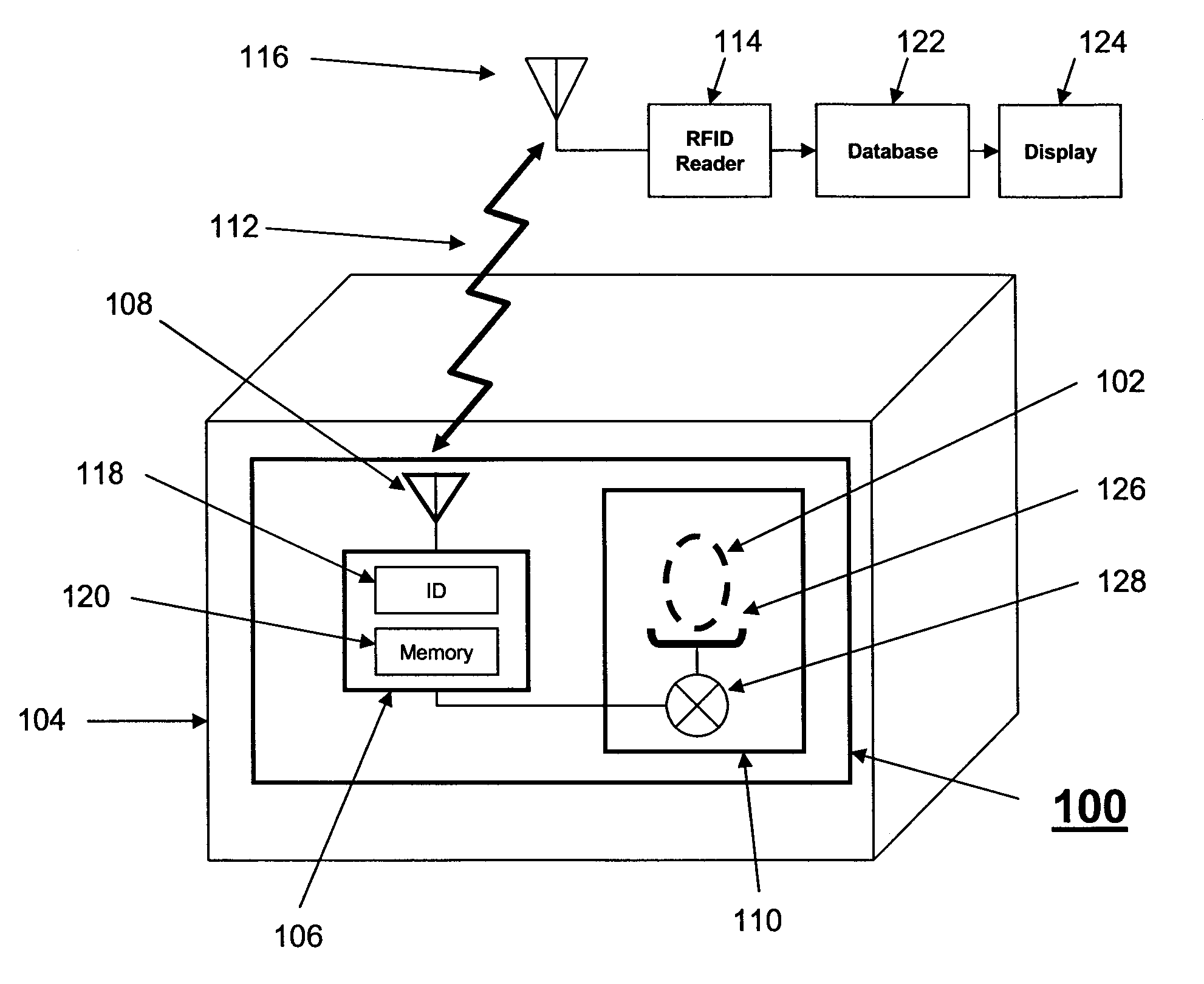
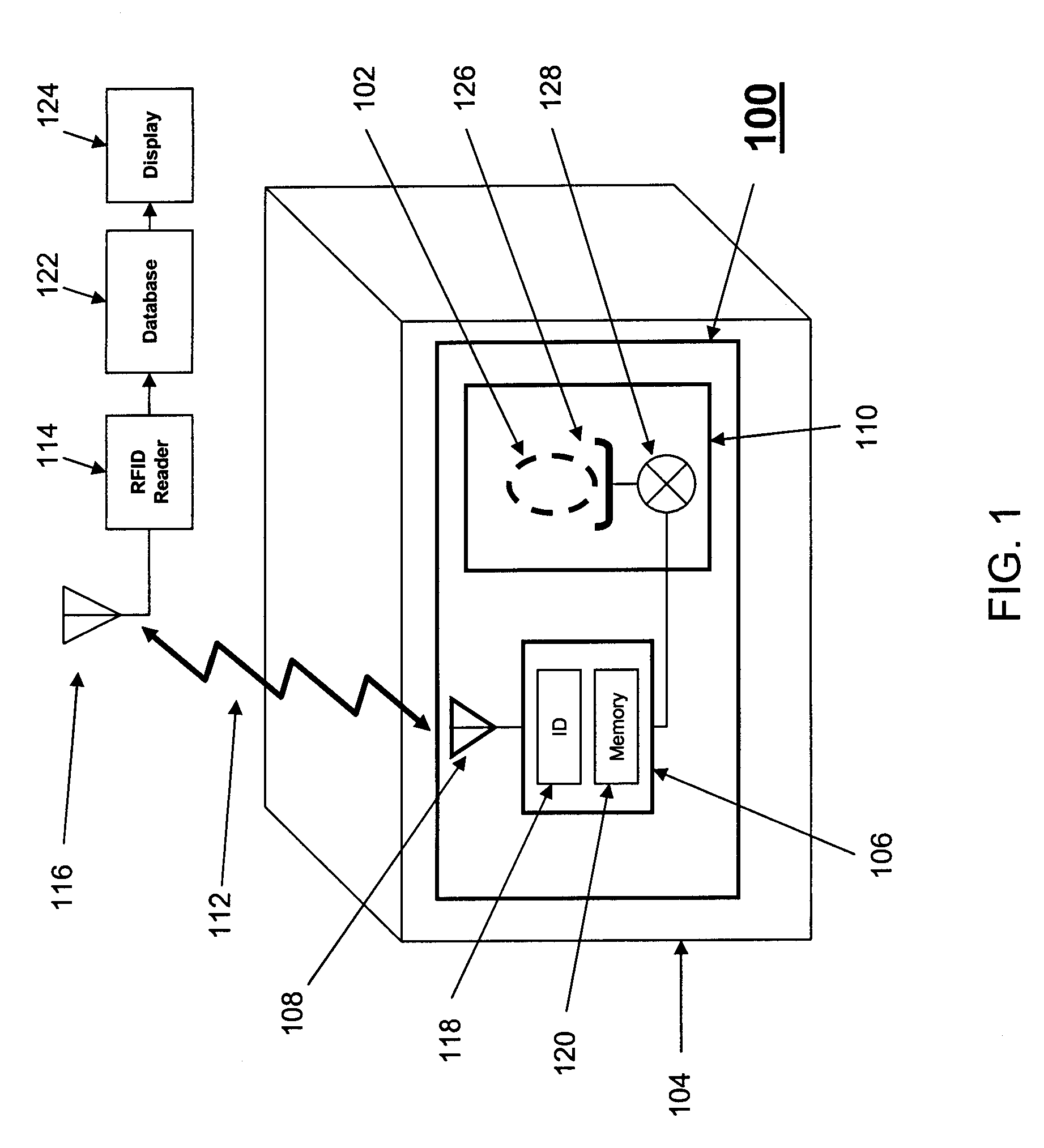
[0023]FIG. 1 depicts an exemplary schematic of a radio frequency identification (RFID) inventory device 100 for inventorying items or objects 102 stored in container 104. The inventory device 100 illustratively includes a RFID chip 106 coupled to an antenna 108 and at least one sensor 110. In the various embodiments, the antenna 108 is tuned to operate at a particular frequency and to support wireless interrogation 112 by a RFID reader 114 through a reader antenna 116. The RFID chip 106 can be configured to be responsive to the wireless interrogation 112, allowing the RFID reader 114 to access a unique identifier e...


PUM


Abstract

A radio frequency identification (RFID) inventory device attached to a container for tracking quantities of objects stored in the container having an antenna supporting wireless interrogation by an external RFID reader, a RFID chip coupled to the antenna having an embedded unique identifier and a memory element, where the RFID chip is adapted to store in the memory element at least one quantity value and to allow an external reader to wirelessly collect the identifier and at least one quantity value in response to said wireless interrogation, and one or more sensors coupled to the RFID chip, where the sensors are configured to send at least one signal to the RFID chip in response to a change in quantities of objects in the container and where the RFID chip is configured to update at least one quantity value stored in response to a signal from the sensors.

Description

FIELD OF THE INVENTION[0001]The present invention is related to the field of inventory devices and methods and more particularly, to an RFID inventory device and use thereof.BACKGROUND OF THE INVENTION[0002]Radio frequency identification (RFID) technology provides the ability to track individual items through a supply chain from a manufacturer to the consumer. However, the ability to tag individual items can be limited in some circumstances. First, the ability to physically tag individual items can be limited. Although relatively large items can be easily tagged using RFID technology, the physical space on smaller items is often limited, making tagging difficult or impossible. One solution proposed is the use of RFID ink technology, which allows an RFID tag to be printed on a small object. Printed RFID tags can be used on the surface of a syringe, for example, or any other object with a small surface area. However, even if tagging is possible, tagging may be undesirable, as it can a...

Claims


Application Information

Patent Timeline
IPC IPC(8): G08B13/14
CPCG01G15/00G01G19/42G06K19/0716G06K17/00G06K17/0029G01G23/3728
Inventor JONES, ANDREW R.BOSS, GREGORY J.SMITH, DONNIE A.HAMILTON, RICK A.MCCONNELL, KEVIN C.
Owner IBM CORP
Why Eureka
Try Eureka