Laser projection apparatus

a projection apparatus and laser technology, applied in projectors, color television details, instruments, etc., can solve the problems of optical elements increasing in size, differences in resolution, and screen brightness increasing, and achieve the effect of facilitating downsize, successful projection characteristics and brightness

Inactive Publication Date: 2008-07-03
KONICA MINOLTA OPTO
View PDF5 Cites 18 Cited by
  • Summary
  • Abstract
  • Description
  • Claims
  • Application Information

AI Technical Summary

Benefits of technology

[0011]Accordingly, an object of the present invention is to provide a laser projection apparatus using a projection optical system which is easy to downsize, has velocity uniformity (arcsine characteristic) and has successful projection characteristics and brightness.

Problems solved by technology

This leads to problems, as commonly known, that the brightness of screen becomes higher in its peripheries than in its center, or that there may occur differences in resolution between the center and the peripheries on condition that the modulation rate of the light source is maintained constant.
However, in the optical system of Patent Document 1 described above, in which a plurality of scanning mirrors are used as a reflecting optical system, there arises a need for distances between the scanning mirrors to separate rays of light from one another, and optical elements increase in size with increasing distances from the deflection scanning means so that the whole projection optical system inevitably increases in size.
Therefore, in spite of four reflecting surfaces used in the system, the final-stage reflecting surface is not so large in size, compared with the system of Patent Document 1, but there are some unavoidable problems, for example, 1) the optical system in itself is increased in size because of as many as four scanning mirrors, 2) it is difficult to position four curved-surface mirrors with high precision, and 3) an optical system up to the light source image is increased in size because the light source image to be once formed in the optical path is distant from the deflection scanning means.

Method used


Image

  • Laser projection apparatus
  • Laser projection apparatus
  • Laser projection apparatus

Examples


first embodiment

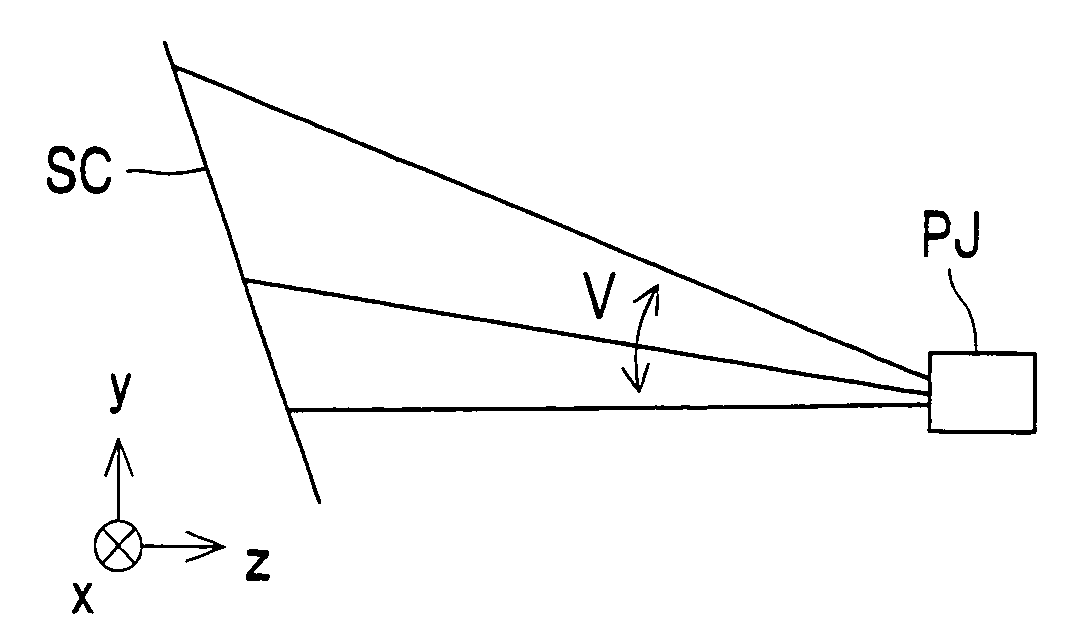
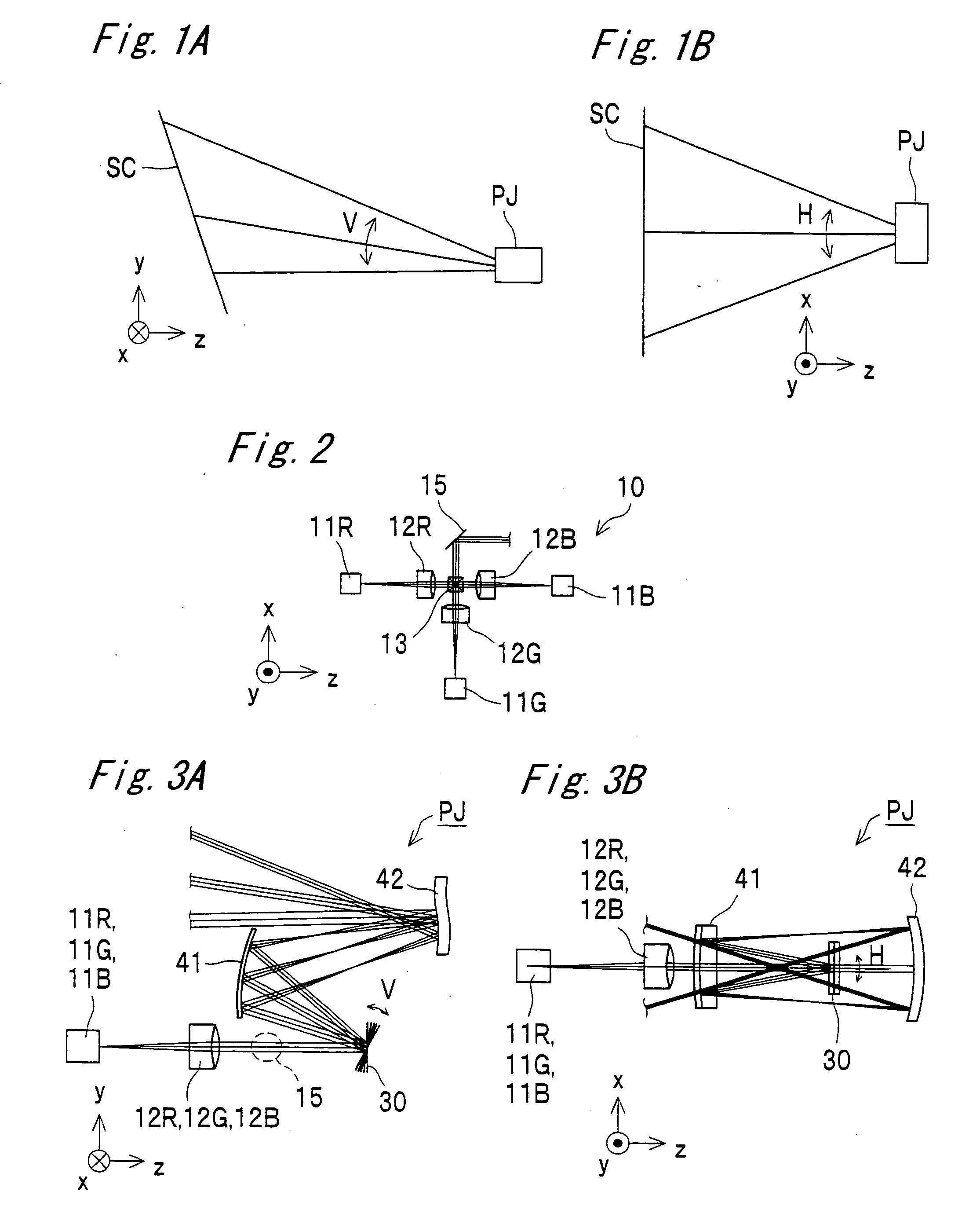
[0123]FIGS. 1A and 1B are overall views showing a first embodiment of the present invention, where FIG. 1A is a side view thereof and FIG. 1B is a plan view thereof. A laser projection apparatus PJ projects a light beam, subjected to intensity modulation based on an image signal, scanning in the V (Vertical) direction and the H (Horizontal) direction to form a raster scan image on a screen SC. As shown in FIG. 1A, projection to the screen SC from an oblique down side allows the laser projection apparatus PJ to be kept out of the field of view of a viewer.

[0124]FIG. 2 is a configurational view showing an example of a light source unit in the laser projection apparatus PJ. The light source unit 10 includes a laser device 11R for generating R (Red) light, a laser device 11G for generating G (Green) light, a laser device 11B for generating B (Blue) light, an incident optical system 12R for supplying the R light derived from the laser device 11R to a scanning device so that an optimum ob...

second embodiment

[0157]FIGS. 8A and 8B are overall views showing a second embodiment of the invention, where FIG. 8A is a side view thereof and FIG. 8B is a plan view thereof. A laser projection apparatus PJ projects a light beam, subjected to intensity modulation based on an image signal, scanning in the V (Vertical) direction and the H (Horizontal) direction to form a raster scan image on the screen SC. As shown in FIG. 8A, projection to the screen SC from an oblique down side allows the laser projection apparatus PJ to be kept out of the field of view of a viewer.

[0158]FIG. 9 is a configurational view showing another example of the light source unit in the laser projection apparatus PJ. The light source unit 10 includes a laser device 11R for generating R (Red) light, a laser device 11G for generating G (Green) light, a laser device 11B for generating B (Blue) light, a color synthesizing device 13 for coaxially synthesizing R light, G light and B light together, an incident optical system 14 for ...


PUM


Abstract

A laser projection apparatus includes: laser devices; incident optical systems, each of which is supplied with light beam from the laser device; a scanning device for two-dimensionally scanning the light beam; and a projection optical system for projecting the light beam from the scanning device onto a screen; wherein the scanning device includes a resonant drive mirror for performing deflection in a main scanning direction, and the projection optical system includes at least two nonaxisymmetric-shaped reflecting mirrors and a light source image is present between the first mirror, which is most closest to the scanning device, and the second mirror, thereby achieving a laser projection apparatus using a projection optical system which is easy to downsize, has velocity uniformity and has successful projection characteristics and brightness.

Description

BACKGROUND OF THE INVENTION[0001]1. Field of the Invention[0002]The present invention relates to a laser projection apparatus for projecting an image onto a screen by two-dimensional scanning of light, the apparatus being applicable to image projection apparatuses such as pocket projectors, data projectors and rear projection televisions.[0003]2. Description of the Related Art[0004]Small-size image projection apparatuses for projecting an image by two-dimensional deflection scanning of light derived from a light source have been proposed in various types (e.g., the following Patent Documents 1 and 2). Generally, galvanomirrors or MEMS (Micro Electro Mechanical Systems) mirrors are used as an optical scanning means. In order that a galvanomirror or MEMS mirror is used with high speed and large amplitude (i.e., mechanical deflection angle), a drive method using resonance is employed. However, it is known that using such a resonant drive method would involve decreasing in the scanning ...

Claims


Application Information

Patent Timeline
Patent Type & Authority Applications(United States)
IPC IPC(8): G03B21/28
CPCG02B26/0858G02B26/101H04N9/3129G03B21/28G02B27/0031
Inventor KONNO, KENJIFUJIYO, ICHIRO
Owner KONICA MINOLTA OPTO
Why Eureka
Try Eureka