Double Side-Bar Conveyor or Digger Chain

a conveyor chain and side bar technology, applied in the field of conveyor chains, can solve the problems of drive shafts, link damage, tedious and time-consuming assembly of such constraining devices, etc., and achieve the effect of easy repair, easy removal and replacement, and easy removal and replacemen

Inactive Publication Date: 2008-07-10
RIRIE MAX H
View PDF19 Cites 6 Cited by
  • Summary
  • Abstract
  • Description
  • Claims
  • Application Information

AI Technical Summary

Benefits of technology

[0010]Because of this construction, the conveyor chain can be easily repaired in the field with a minimum of tools. Specifically, a rod can be removed by merely using wrenches or other tools to loosen and / or remove a single link's keeper element, then the link can be rotated 90 degrees and the rod may then be moved into the wide end of the keyhole and easily removed and replaced. Since all the links in the chain are identical, any damaged rod or other damaged part may be easily removed and replaced in the field with a minimum of tools and time, and with a minimum of spare parts required. The simple construction reduces cost, and the savings in time for repairs also provides great cost benefits. The ends of the chain are smooth, preventing damage to the inside of the conveyor. Additionally, damage to crops is minimized when compared to hook chain coveyors.
[0011]To facilitate ease of assembly, pairs of side bars may be permanently connected together. The side bars may be welded or spot welded together, and this reduces the number of individual parts to be handled in assembly and has no effect on the performance of the chain. Although the described conveyor chain is particularly suitable for use in agricultural situations, those of skill in the art may readily appreciate that the chain conveyor may be adapted for use in other situations where a conveyor having flight rods is desirable.

Problems solved by technology

The assembly of such constraining devices is tedious and time-consuming, and frequently no provision is made for limiting inward movement of the links on the rods.
When such movement occurs, the ends of the rods protrude outwardly of the sides of the chain where they are exposed to damage by or to cause damage by catching on adjacent conveyor supporting structure or becoming entangled with vines, weeds, and other trash pulled into the conveyor.
Also during such inward displacement, the links are subject to being damaged from engagement with drive sprockets, idlers, or other conveyor supporting structure.
These chains are characterized by entanglement with crops and debris during operation, lack of desired durability, a tendency to misalign and to incur accompanying stress and wear as well as to impose undue stress and wear on the mounting sprockets therefore.
These belts are typically weaker than the chains, and require a different type of linkage where belt elements are joined, and the linkage typically forms a weak spot in the belt that is even more prone to failure.
Each of the conventional conveyors, whether using belts or chains, has other difficulties beyond those described above.
It sometimes occurs that the rods on the conveyor or digger become damaged and require replacement.
On many of the conveyors, changing out damaged flight rods or other damaged parts is so impractical that it is simpler to always carry an extra conveyor belt or chain, and when damage occurs replace the entire belt or chain.
Repairs often require the use of special tools and may be extremely labor intensive.
Additionally, many conventional conveyors use a large multitude of specialized parts or require the replacement of large sections when even a small portion of the conveyor is damaged.
Each of these problems can greatly increase the cost of using the conveyor in harvesting.

Method used


Image

  • Double Side-Bar Conveyor or Digger Chain
  • Double Side-Bar Conveyor or Digger Chain
  • Double Side-Bar Conveyor or Digger Chain

Examples


Embodiment Construction

[0025]Referring now to the Figures, a description of the embodiments of the present invention will be given. It is expected that the present invention may take many other forms and shapes, hence the following disclosure is intended to be illustrative and not limiting, and the scope of the invention should be determined by reference to the appended claims.

[0026]In the specification and in the claims, the terms “chain,”“conveyor chain,” and “digger chain” shall be synonymous and interchangeable. The terms “rod” and “flight rod” shall be synonymous and interchangeable, and may refer to rods of any length and diameter, and also may include rods of varying materials and strengths.

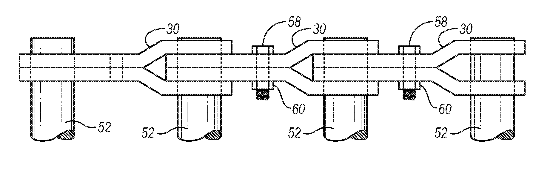
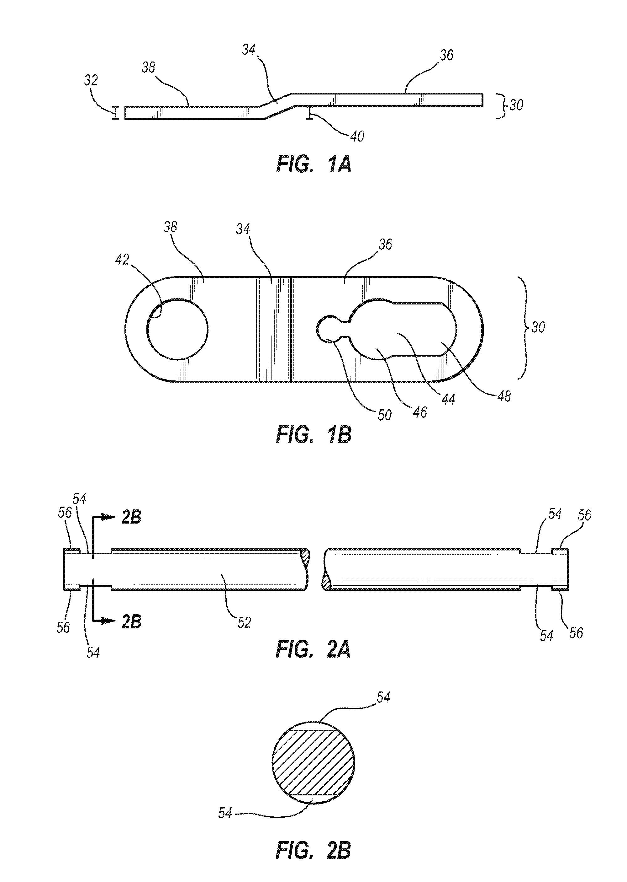
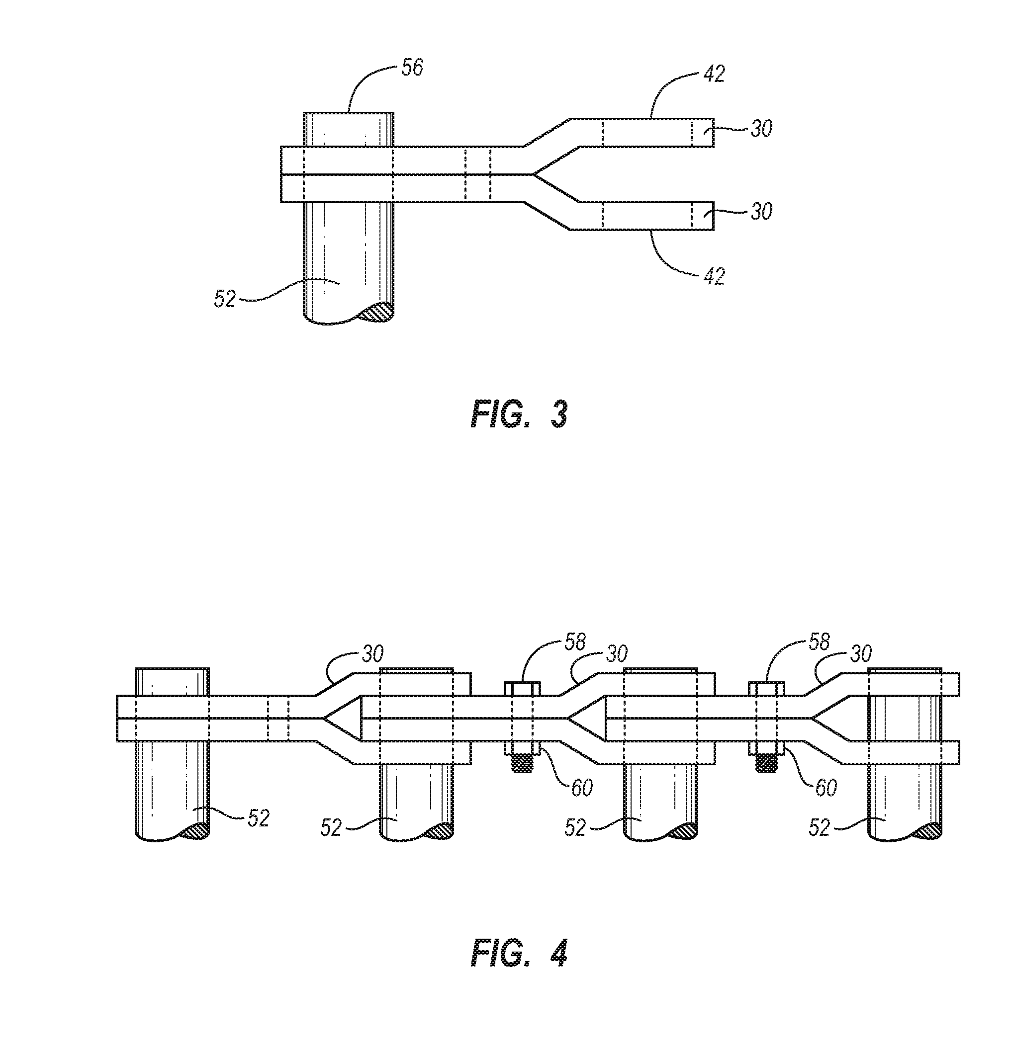
[0027]FIGS. 1a and 1b show side and top views of a side bar 30 in accordance with one embodiment of the present invention. The side bar 30 is manufactured from a durable material sufficiently strong to hold up to the rigors of use as the linking member of a conveyor chain. Typically, the side bar 30 is made of m...


PUM


Abstract

An agricultural conveyor chain with links is disclosed, each link including a rod connected on either end to a pair of side bars, each side bar having a circular hole and a keyhole and the pair of side bars forming a Y shape to interact with the rod and side bars of the next link. The connection between the rod and side bars is provided by notches in the rod that interact with the narrow ends of keyholes in the side bars. Each rod also interacts with the circular hole of the side bars from the next link, and a nut and bolt in the pair of side bars prevents the rod from sliding out of the narrow end of the keyholes. This provides a rotatable but secure linkage between links, simple repairs, and ends of the rods that are substantially flush with the outside of the side bars.

Description

BACKGROUND OF THE INVENTION[0001]1. Field of the Invention[0002]The present invention relates to a conveyor chain for use in potato harvesters and other similar agricultural harvesting machines, and more particularly to such a conveyor chain having spaced material supporting flight rods and articulated connecting links which hold the supporting rods in assembly by pairs of side bars on each end of the flight rods.[0003]2. Background and Related Art[0004]Conventional conveyor chains employed on potato harvesters and the like usually consist of a plurality of elongated spaced flight rods interconnected at their opposite ends by sets of continuous chains of articulated links. The rods usually employ large flanged integral heads, removable lock nuts, cotter keys, or other similar constraining devices to prevent the links from sliding off the ends of the rods. The assembly of such constraining devices is tedious and time-consuming, and frequently no provision is made for limiting inward ...

Claims


Application Information

Patent Timeline
Patent Type & Authority Applications(United States)
IPC IPC(8): B65G17/06
CPCA01D17/10B65G17/42A01D2017/103
Inventor RIRIE, MAX H.
Owner RIRIE MAX H
Why Eureka
Try Eureka